 TOP
TOPChapter 1 Introduction to Pneumatics
Goto Zulie teacher teaching network Pneumatic hydraulic control practice
Pneumatics , is the use of compressed air has pressure energy, as the various types of mechanical control purposes, in order to save manpower and improve productivity, one of the main sources of power automation.
”@
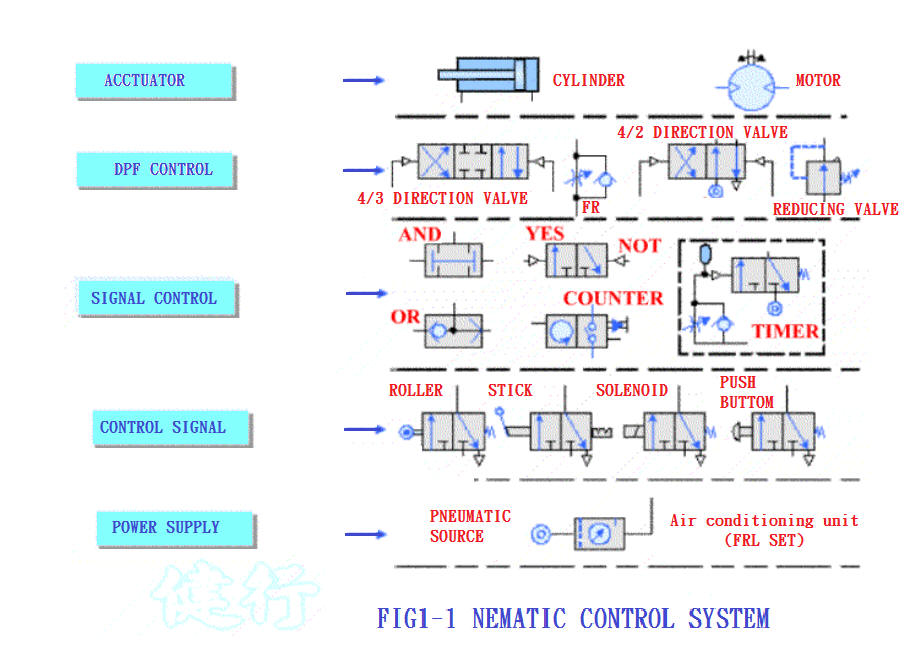
1-1. Signal flow of Pneumatic control system P3 TOP
1-2. Characteristics of Pneumatic System P5
1. Easy to get
2.Good explosion resistance
3. Easy transmission
4. Easy storage
5. Fast speed
6. Overload safety
7. Clean
8. Easy to adjust
9. Simple structure
10. Adjustable stroke
11. Can produce linear motion directly
12. Wide operating temperature
”@
1. Higher cost
2. Easy to leak
3. Compressible
4. Lack of lubricity
5. Limited output
6. Large Exhaust noise
1-3. Economic benefits of pneumatic system P6
Pneumatic systems are a relatively expensive source of power. However, from the perspective of long-term investment, the use of Pneumatic instead of labor can improve the efficiency of production and make it easier to master schedules. Long-term costs are more cost-effective.
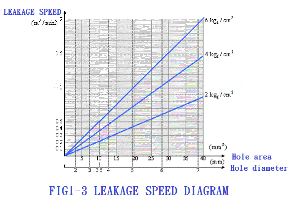
1-4. Impact of air leakage on air pressure system P7
1-5. Basic physical principles applied to Pneumatic control P9
1-5.1 Composition of air
|
Type of gas |
|
|
Ar |
|
Ne |
He |
|
Volume (%) |
78.09 |
20.95 |
0.93 |
0.030 |
0.0018 |
0.00052 |
|
Weight (%) |
75.52 |
23.15 |
1.28 |
0.046 |
0.0012 |
0.00007 |
Standard state (ANR) : temperature 20 ¢J
: absolute pressure 760 mmHg
: relative humidity 65%
:
specific gravity of air 1.293Kg / m 3
”@”@”@”@”@”@”@”@”@”@”@”@”@”@”@”@”@”@”@
Reference state: temperature 0 ¢J
: absolute pressure 760 mmHg
: dry state ( relative
humidity 0%)
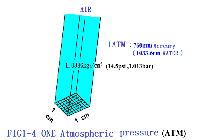
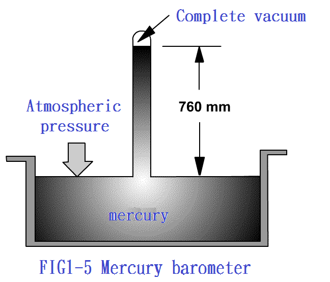
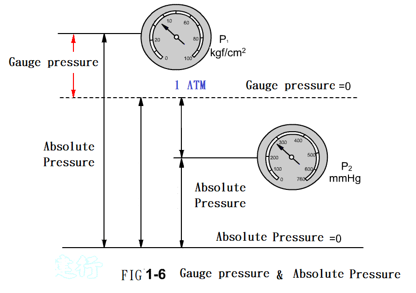
1-5.2 Definition and Unit of
Pressure P


1-6. Pressure range used by the pneumatic system P12
1. Low pressure system: 0.5 ~ 500 mbar
2. Medium pressure system: 1 ~ 4 bar
3. Normal pressure system: 3 ~ 8 bar
4. High pressure system: above 10 bar
”@
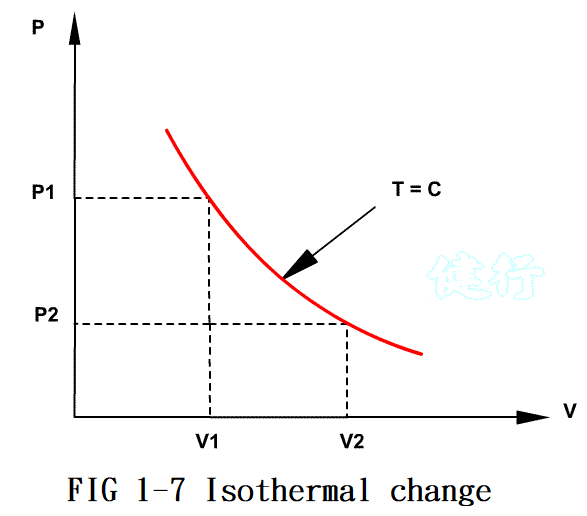
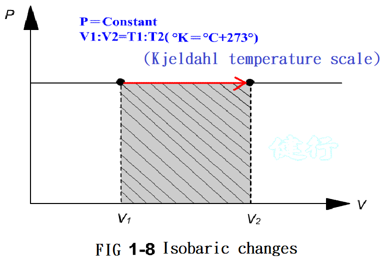
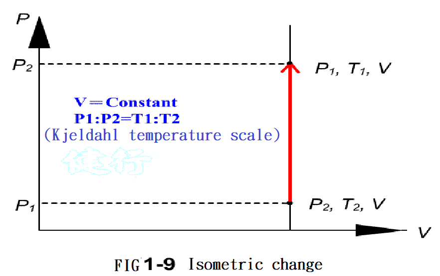
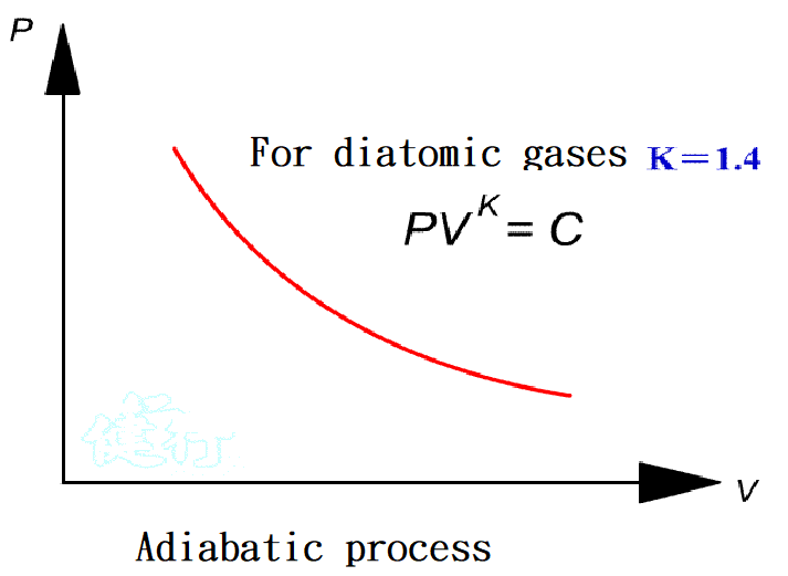
1-7. Important Laws Related to Pneumatic P13
”@
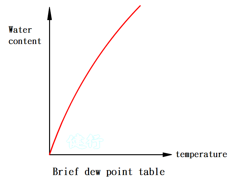
1-8. Air humidity and dew point P16
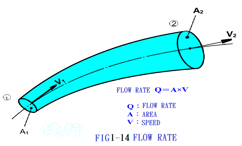
1-9. Air flow P18
Flow formula: Q = A ”P V
Where Q : flow rate;
A : cross-sectional area of the pipeline;
V : flow speed.
”@ Such a relationship are called the law of continuity.
”@


GOTO Chapter 2 Introduction to Components of Pneumatic System
Goto Zulie teacher teaching network, Pneumatic hydraulic control practice
FIN