ˇ@
Pneumatic & Hydraulic control practice
ˇ@
CHAPTER 1 TRADITIONAL PNEUMATIC CONTROL
ˇ@
1-1 Preface
ˇ@
Traditional Pneumatic control uses general
Pneumatic control components to control the pressure, Direction, and
Flow rate of the compressed Pnenumatic provided by the Pnenumatic
Compressor , and then adjusts the
pressure after accumulating, timing, counting or processing to vacuum with
auxiliary components The compressed Pnenumatic is sent to pneumatic cylinders,
pneumatic motors, pneumatic rotary cylinders, or vacuum suction cups and other
pneumatic action components, which are used as the output of the system to
provide power for processing machines or industrial automation systems.
ˇ@
1-1.1 pressure control valve (Pressure
control valve)
101 sequence valve : it is a Normally Closed(NC) valve, and when it is
not in motion, there valve is closed ; when the inlet pressure is greater than
the setting value of the adjustment spring, the valve opens.


ˇ@
ˇ@
102 Pressure reducing valve : It is a Normally Open(NO) valve. When it is not
actuated, the valve is opens . The pressure
drop of the outlet secondary pressure can be set by adjust the pressure
adjusting spring.
ˇ@


ˇ@
ˇ@
103 Drain valve : It is a Normally Closed (NC) valve. When it is not operating, It is
closed ; when the inlet pressure is greater than the setting value of the
adjusting spring, the valve opens and the pressure is released. It is often used
for the safety pressure setting of the system.


http://www.aliexpress.com/popular/manual-relief-valve.html
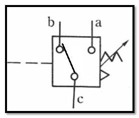
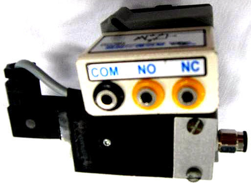
104 pressure switch: It is a pneumatic-electric conversion element. When it is not activated,
the circuit c-b on and c-a off ;
when the inlet pressure is higher than the setting value of the adjustment
spring, the circuit switches to c-a on and c-b off.
ˇ@
1-1.2
Direction control valve (
Direction control valve)
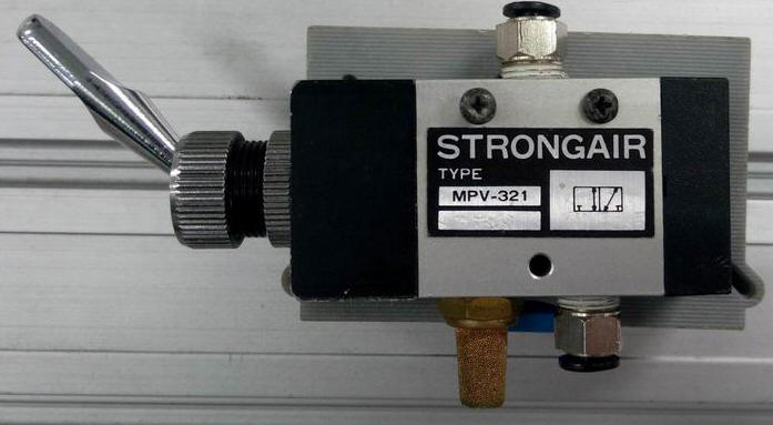
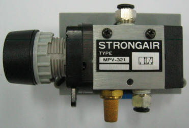
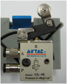
Operation method:

ˇ@

ˇ@
ˇ@

ˇ@

ˇ@
201 Two-port two-position (2/2) Directional valve:
It has two forms : Normally
Open (NO) and Normally Closed (NC) . It is often used to control the opening or
closing of the Pnenumatic pipe.
ˇ@
ˇ@
202 Three-port two-position (3/2) Directional valve:
It has two types of Normally
Open(NO) (NO) and Normally Closed(NC) (NC) . It is often used to control single-acting cylinders
or single-acting pneumatic motors. It can also be used to control the opening
or decompression of pneumatic lines.
ˇ@


ˇ@
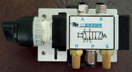
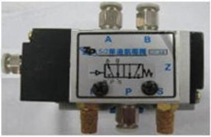
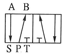
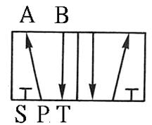
203 five-port two-position (5/5) Directional valve:
a Directional control element, often used for the
control of double-acting pneumatic cylinders or double-acting pneumatic motors.
It can also be used for cascade design of the return valve for the purpose of
changing the stage. The difference between right-hand drive and left-hand drive
is similar between European and American regulations. There are also
differences between left position Pˇ÷B pass, right position Pˇ÷A pass, left position Pˇ÷A pass, and right position Pˇ÷B pass.
ˇ@
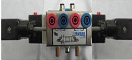
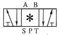
204 five-port three-position Directional valve:
Directional control element, often used for the control
of double-acting pneumatic cylinders or double-acting pneumatic motors;
depending on the control requirements, it has a neutral shut-off lock, a
neutral exhaust pressure and a neutral position Different forms such as
bilateral Pnenumatic intake.


205 check valve: also known as check valve. It is a one-way valve with a forward path and
no reverse Direction. It is often used to prevent back Flow, pressure lock, or
use with a control valve to establish a bypass path ; if there is an
occasional reverse For access requirements, a pilot check valve can be used to
open it with pilot pressure.
ˇ@


ˇ@

1-1.3
Flow control valve
301 Throttle Valve: Reduce the Flow channel area and adjust the
Pnenumatic Flow to achieve the purpose of adjusting the actuator speed.
ˇ@

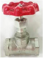
302 STOP valve: also known as on-off valve, which controls the opening and closing of
the Flow channel.
ˇ@


http://www.hj-hg.com.tw/product-detail-208439.html
ˇ@
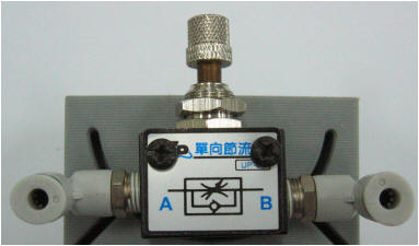
303 comes with a check throttle valve: also known as a Flow regulator (FR) , for one-way speed regulation.
ˇ@

ˇ@
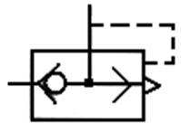
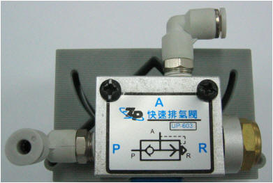
304 Quick exhaust valve: Pneumatic P enters A out, A enters R out ( exhaust ) ; A port is installed at the exhaust port of the actuator to provide a quick
exhaust path to increase the speed of the actuator.
ˇ@
ˇ@
ˇ@
ˇ@
ˇ@
1-1.4 pneumatic actuator
ˇ@
401 Pnenumatic Cylinder: The piston is driven by Pneumatic, which converts
Pneumatic energy into pushing and pulling mechanical energy components.
ˇ@
ˇ@


ˇ@
ˇ@
ˇ@
402
Pneumatic Motor: A component that converts Pneumatic energy into
continuous rotating mechanical energy.
ˇ@
ˇ@
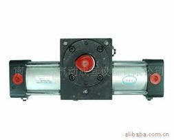
403 rotary cylinder: also known as a rotary cylinder , a
component that converts Pneumatic energy into a fixed-angle rotating
mechanical energy.
ˇ@

http://www.68jd.com/biz/2009522/55587.html

ˇ@
1-1.5 auxiliary element
ˇ@
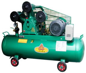
501 Pneumatic
Source : Provides
compressed Pnenumatic as the driving force for the operation of the Pneumatic
system.
ˇ@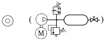
 ˇ@
ˇ@
502
Pnenumatic Recervoir / Accumulator : Multi-Pnenumatic reservoir for storing compressed Pnenumatic conveyed
to the compressor; used for Stabilize,
supplement Flow and act as a temporary pressure source.
ˇ@


ˇ@
ˇ@
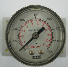
503 Pressure Gauge : Based on the principle of Bourdon tube , it displays the pressure value in the system.
ˇ@

ˇ@
504 Timing valve (TIMER): , the guiding pressure uses the principle of throttling
and Pnenumatic chamber charging to achieve the purpose of timing actuation. It
has two control modes: timing actuation and timing reset, There are two types
of actions, as well as Normally Closed(NC) and normally Open(NO).
timing actuation timing valve
.
ˇ@
Timing reset NO timing
valve


CNS SYMBOL
ˇ@
ˇ@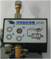
ˇ@
505 Pneumatic Pipe : The pipe fittings is for conveying Pneumatic, beside the difference in material and size, are
divided into hard pipe and hose.
ˇ@
ˇ@
506 three-piece combination (FRL combination): Pnenumatic conditioning components, including Filter, pressure Regulator, and Lubricator
in sequence, also known as three-point combination.
ˇ@

ˇ@
ˇ@
507 Counting valve (Counter) : Uses the on / off of the input pilot Pneumatic to
count the times. When the on / off times reach the set value, the valve witches; where P is the pressure Pnenumatic inlet, A is the Pneumatic outlet, and C (Z ) Is the counting terminal, R (Y) is the Pneumatic zero return (RESET)
terminal, and RST is
the manual zero return.

ˇ@

Decrement (-) type counter
Increment (+) type counter
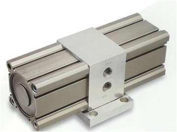
508 pressure
increaser: apply pressure to the big piston to push the small
piston, and use the characteristic that the pressure is inversely proportional
to the piston area to achieve the purpose of boosting.
ˇ@

ˇ@
ˇ@
ˇ@
509 silencer : installed at the exhaust port of the pneumatic component, to achieve
the purpose of silence by cover,absorption and interference.
ˇ@


SHAKO
https://www.shako.com.tw/webls-zh-tw/accessories/09.htm
510 shuttle valve : logical OR , C = A+B ; when there is pressure input at either end of A and B , there is pressure output at end C.


ˇ@

51 1 Double-pressure valve : logical AND , C = AˇŃB ; when both ends A and B have pressure input, there is pressure
output at end C.


ˇ@
512 vacuum generator : It is driven by compressed Pnenumatic using
the principle of venturi. When the Pneumatic Flows through the nozzle, the Flow
rate increases, and suction is generated at the opening due to the pressure
difference. Generally, it can generate a vacuum pressure of about
tens of KPa
( a few tenths of a bar) .
ˇ@

ˇ@
ˇ@
ˇ@
ˇ@
1-2 Precautions
1. The operation should be preceded by all the Flow control valve to the
minimum; delay valve, the valve zero count; and check whether there is water
inside the bowl FRL, if the bolts loosen the drain cup bottom, and the
pressure is adjusted 3~8KGf/cm 2 .
2. When connecting the
circuit, the pressure source should be closed to prevent a large amount of Pnenumatic leakage
or the pipeline swinging and hurting people.
3. When assembling and disassembling the pneumatic tube, press
down the quick-disconnect joint before pulling it out . In case of a new pipe or joint with a tight bite, it is not easy
to pull out the quick release joint by pressing down. Push the Pnenumatic tube
forward to disengage the inverted teeth before pulling out the Pnenumatic tube.
Do not pull hard to avoid damage to the Pnenumatic tube wall and joints. .
4. After connecting the circuit, check whether all the connectors are
properly connected before turning on the Pneumatic source to prevent the
pipeline from tripping when the pressure is connected.
5. The unused components and Pneumatic tubes on the machine should be
placed properly and do not fall to the ground.
6. Do not blow Pneumatic to others, so as to avoid injury caused by Pneumatic
or impurities in the pneumatic.
7. The
solid and dashed lines in the circuit are pneumatic pipelines. Generally
speaking, the solid line is the operating pressure, and the dashed line is the
pilot pressure. When the two lines intersect and are not connected, no
cross-line processing is performed. If they are connected, the intersection is
indicated by a dot.
8. When assembling the control valve, confirm the
inlet and outlet positions of each valve , and mark the piping according
to the Direction of the arrow or the pressure input end ( P) , output end ( A , B) , pilot pressure ( X , Y), etc., so as to avoid incorrect connection.
It has a function; if the control valve leaks a lot when the pressure is turned
on, it is mostly caused by the reverse connection of the inlet and outlet
pipelines.
9. When assembling the actuator, confirm the extension Direction of the
pneumatic cylinder, the inlet and outlet of the pneumatic motor or the rotary
cylinder, the normal pressure output port of the Directional control valve and
the installation position of the roller valve (the double roller valve is installed on the stroke of the pneumatic cylinder
At the end, the installation position of the single roller valve must be moved
to the inside ) and the contact Direction of
the roller valve (the roller is on the outside ) .
10. The assembly way throttle valve when the bypass check confirmation
opening Direction, the speed control loop does understand the way the intake throttle ( metered into, Meter in) or an
exhaust throttle ( measured out, Meter OUT) .
11. If
there is any abnormal movement or situation, immediately press the emergency
s (EMS) button or turn off the Pneumatic source, and then turn it on again after
removing the abnormal situation.
12. After the circuit is connected, the pressure should be started after
confirming that there are no obstacles on the pneumatic cylinder stroke; do not
s or place objects in the pneumatic cylinder stroke to avoid danger or damage
during operation.
13. After starting the circuit, you should follow the operating steps
and record the operation status one by one. If the system does not operate at
all or does not operate correctly, you can turn off the pressure and check the
Pneumatic circuit and the aforementioned precautions to find out the errors and
eliminate the obstacles. After removing the obstacle, restart the pressure
start circuit again.
14. After all internships are completed, the Pneumatic source should be turned off, the
pipelines and components should
be collected,
the work surface should
be cleaned,
and the use record form should
be filled
in.
ˇ@
ˇ@
1-3-1ˇ@basic
application --- three-point combination basic
adjustment exercise
Practice purpose: to understand the
characteristics of three-point combined filtration, pressure regulation
and lubrication .
1-3-2 Direction control --- Single-acting cylinder control circuit
Practice purpose: to understand the motion control
of a single-acting cylinder.
A.
Direct control
1-3-3 Direction control --- Double-acting cylinder control circuit
Practice purpose: to understand how to switch
the Direction of a double-acting pneumatic cylinder with a button valve.
A. Single rod cylinder manual Direct
operation circuit
B. Double rod cylinder manual Direct
operation circuit
C. Double-acting cylinder pulse pilot pressure in
Direct control loop
1-3-4 Directional Control ---5/3 Directional Valve Control Circuit
Practice purpose: to understand the role of
pilot pressure and the Direction switching of the pneumatic cylinder by the five-port
three-position valve.
A. 5/3
Directional valve stationary waveguide pressure control loop
B. 5/3 Directional valve pulse pressure control circuit ( Pneumatic self-protection )
C. 3/2
Directional valve stationary waveguide pressure in
Direct control loop
1-3-5 Direction control --- Double-acting cylinder EMS emergency s control loop
Practice purpose: to understand the application
of pneumatic cylinder emergency s control.
A.
After pressing the emergency s, continue to operate
the circuit after the emergency s is released
B. Emergency return to the loop after
pressing
C. The return control
loop after the emergency s is released after pressing
1-3-6 Flow control --- measuring in and out speed control loop
Internship purpose: to understand the principle
of speed control with check throttle valve.
A. Single-acting
cylinder manual control
B. Double-acting
cylinder speed control circuit
C. Double-acting cylinder reciprocating speed
control circuit
D. Double-acting cylinder automatic reciprocating
speed control circuit
1-3-7 Flow control --- quick exhaust valve action circuit
Internship purpose: to understand the operating
principle of rapid exhaust valve speed increase.
1-3-8ˇ@Pressure
control --- sequence valve actuation
control loop
Internship purpose: to understand the operating
characteristics of sequence valves.
1-3-9 Timing control --- timing action and delay reset control loop
Practice purpose: to understand the application
of timing action timing valve in delayed return.
1-3-10 Timing control --- Double acting cylinder timing action circuit
Internship purpose: to understand the operating
principle of the delay valve.
2. Use equipment and circuits:
ˇ@
1-3-11 Counting control --- double-acting cylinder counting circuit
Practice purpose: to understand the control of
pneumatic cylinder counting.
1-3-12 Series and parallel
control ---AND circuit
Practice purpose: to understand the operating
characteristics of series and parallel circuits.
A. Series control ---AND circuit
B. Parallel control ---OR loop
1-3-13 Load control --- load cylinder locking circuit
Practice purpose: to understand how to use the
pilot check valve to lock the load cylinder.
1-3-14 Load control --- load cylinder balance circuit
Internship purpose: to understand how to balance
the load cylinder with a bilateral pressure-reducing valve.
1-3-15 Negative pressure
control --- vacuum generator application
circuit
Internship purpose: to understand the operating characteristics
of the vacuum generator.
1-3-16
Pressure
Accumulation Control --- Double-acting Cylinder Impact
Circuit (It is recommended to use
a pressure pipe of 6 mm or more for this
circuit )ˇ@
Practice purpose: to understand how to charge a
pressure accumulator to make a pneumatic cylinder produce an impact action.
ˇ@
1-4 Application
circuit
ˇ@
1-4-1 Sequential control --- Double cylinder sequential action circuit
Practice purpose: Two pneumatic cylinders
cooperate with roller valve and pilot valve for sequential action.
A. Double cylinder sequential action circuit
B. Double cylinder sequence action circuit
C. Three-cylinder sequential action circuit
1-4-2 Sequence control --- three-cylinder cascade sequence action loop
The purpose of the practice: the three pneumatic
cylinders cooperate with the roller valve and the pilot valve for sequential
actions.
A. Three-cylinder cascade sequential action
circuit -1
B. Three-cylinder cascade sequential action
circuit -2
C. Three-cylinder cascade sequence action
loop -3
D. Three-cylinder cascade sequence action
loop -4
1-4-3 Sequential control -- Three
double cylinder cascade emergency s return control loop
Practice purpose: Two pneumatic cylinders
cooperate with roller valve, pneumatic pilot valve and 5/2 pressing ( hold ) button valve for emergency s return sequence
action control.
1-4-4 Sequence Control --- Repetitive Action Control Loop
The purpose of practice: Use two pneumatic
cylinders and roller valves to control the repeated actions of
cylinder B.
A. Double cylinder repetitive
action control circuit -1
B. Three cylinder repetitive action control circuit -2
1-4-5 Sequence Control --- Two-stage action control loop
The purpose of the practice: to control the
two-cylinder two-stage movement with the cascade method.
1-4-6 Sequence Control --- Circular Step Sequence Control Loop
The purpose of the practice: to do the
sequential action of the loop with three pneumatic cylinders in conjunction
with the cycle step method.
A. Cycle step sequence control loop -1
1-4-7 Speed control --- Two-stage speed control loop
Practice objective: Two-stage speed action
control of cylinder B with two pneumatic cylinders and a check throttle valve .
1-4-8 Timing control --- delay valve timing loop
The purpose of practice: to use three pneumatic
cylinders with delay valve and roller valve for timing control.
1-4-9 Manual automatic control --- three-cylinder manual / automatic sequence action loop
The purpose of the practice: the three-pneumatic
cylinder and roller valve cooperate with manual automatic control for
sequential actions.
A. Three-cylinder manual / automatic sequence action circuit -1
B. Three-cylinder manual / automatic sequence action circuit -2
C. Three-cylinder manual / automatic sequence action loop -3
1-4-10 Comprehensive control --- timing, parallel control loop
The purpose of practice: three pneumatic
cylinders cooperate with timing and counting valve to do the counting sequence
of the loop.
1-4-11 Comprehensive control --- timing, parallel progress, selection
control loop
The purpose of practice: three pneumatic
cylinders cooperate with timing and counting valve to do the counting sequence
of the loop.
1-4-12 Comprehensive control --- timing, parallel progress, selection, jump control loop
The purpose of practice: three pneumatic
cylinders cooperate with timing and counting valve to do the counting sequence
of the loop.
ˇ@
1-4-13 Counting control --- three-cylinder counting control loop
Purpose of practice: Three pneumatic cylinders
cooperate with counting valve to do the counting sequence of the circuit.
1-4-14 Comprehensive control --- timing and counting control loop
The purpose of practice: three pneumatic cylinders
cooperate with timing and counting valve to do the counting sequence of the
loop.
1-4-15 Comprehensive control --- counting + mode selection control loop
Purpose of practice: Three pneumatic cylinders cooperate
with counting valve to do the counting sequence of the circuit.
[1] The relationship between the switching signal
and the touch: the touch between the pneumatic cylinder and the roller valve during the movement stroke and
the signal switching relationship.
Taking A+B+B - A - as an example, the diagram of the relationship
between the switching signal and the touch is as follows:

[2] Displacement - time graph: a graph indicating the action state of the pneumatic
cylinder. In the figure, the horizontal axis is time, the vertical axis is
displacement, and the slope is speed.
Taking A+Bslow+B - A - as an example, the B cylinder is slow out and fast back, and the displacement - time diagram is as follows:
***************************************************************************************************************************************************************
ˇ@
ˇ@
Appendix Pressure Opening
ˇ@
A. Room
pressure
ˇ@

ˇ@
ˇ@
ˇ@


