?
1. Before
operation, adjust the flow rate of all speed control valves to the
minimum; reset the timer and counter to zero; and check whether there is
water in the three-piece combined filter cup.
If so, loosen the bolt at the bottom of the cup to drain water and adjust
the pressure to .
2.
When wiring
and piping, the power supply and Pneumatic source should be turned
off to avoid
danger and component damage caused by electric shock or pipe explosion.
3.
When connecting
or disconnecting the circuit, hold the connector end and
do not
pull the wire ,
so as not to damage the internal copper wire.
4.
The unused
components and pipelines on the machine platform should be placed
properly and don't fall to the ground.
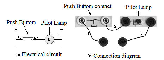
5. If
the power cord is suspected to be disconnected, you can switch the
three-purpose meter to the ohm range for measurement; or connect the
power supply to the indicator light to confirm.
6.
The power
cords should be sorted
and neatly sorted according to their lengths ,
and they should not be tangled or tangled.
After use, put the power cords of the same length together and put them
in place.
7.
When wiring,
you should follow the order of the electrical ladder diagram from left
to right, up and down ,
and donЁІt jump in randomly.
So as not to cause wiring inaccuracy and increase the trouble of
checking the line.
8.
After the Pneumatic and electrical circuits are connected properly, turn on the pressure
source and power
switch and start
the circuit.
If you cannot move or move incorrectly, turn off the Pneumatic and
power switch before making corrections to the circuit.
9. If
there is still no power after turning on the power, confirm whether
there is a short circuit. And check whether the overload
protection is tripped or the fuse is
burned out?
If there
is a possibility of a short circuit, the power should
be turned
off first ,
and the power can
be turned on after removing
the short circuit and obstacles .
10. If
the same
contact appears repeatedly in the loop , separate
wiring and avoid sharing terminals to
reduce the occurrence of short circuits or error signals.
And pay
attention to the order of the wiring of the contacts to avoid short
circuit caused by the connection of the live
wire (+) and
ground wire (-) .
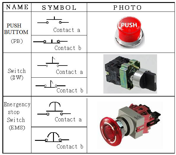
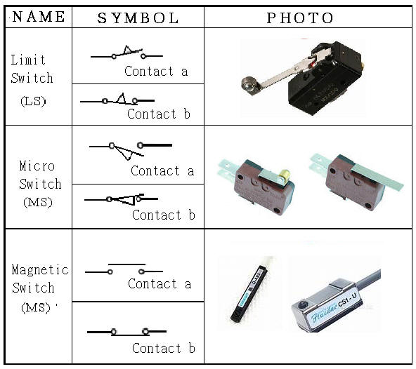
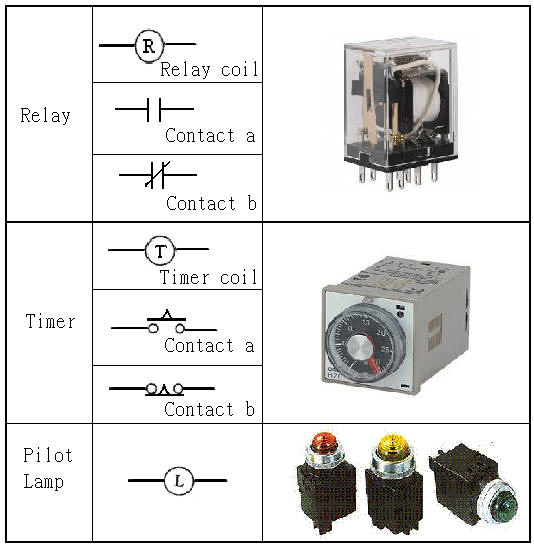
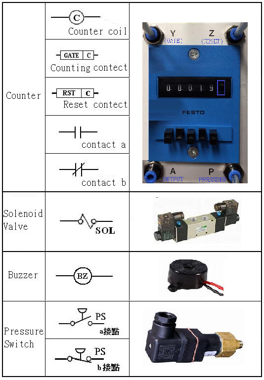
11.
NO normally
open contact (Normally
Open Contact) that
is a contact
point
( Usually
it is open circuit without power, after switching, it is closed circuit
with power ) ,
NC normally
closed contact (Normally
Closed Contact) is the b contact
( Usually
it is closed-circuit energized, after switching, it becomes open-circuit
without energization ) .
12. After
all the operation is completed, should be closed
and the power pressure source and receipt
of the pressure tube and the power supply line, cleaning placement table ,
and indeed
fill usage history table .
Ё@
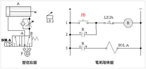
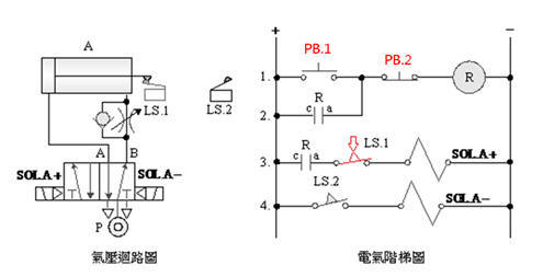
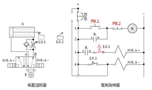
2-3-1Ё@single
solenoid valve control circuit
Internship
purpose: to understand the
operating principle of 5/2 single
solenoid valve.
Use
circuit:
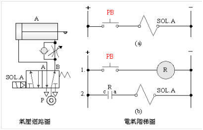
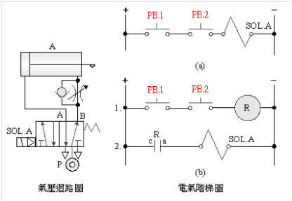
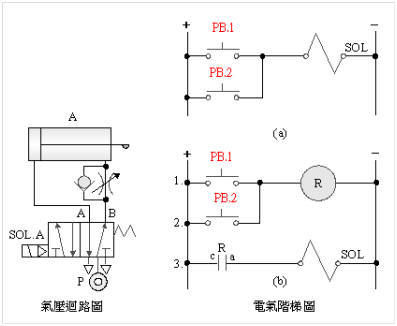
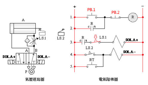
2-3-2Ё@Self-protection ( memory ) control
circuit
Internship
purpose: to understand the operation principle of self-protection
circuit.
Use
circuit:
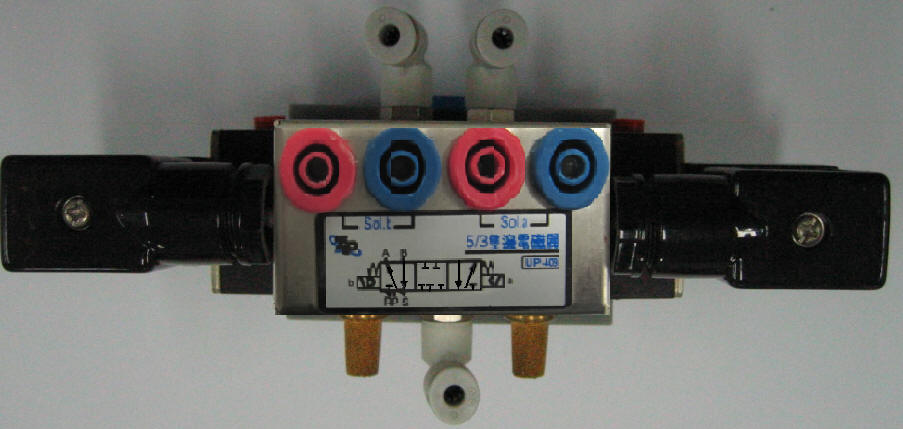
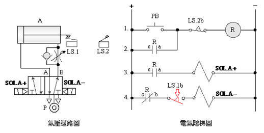
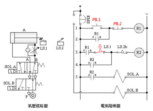
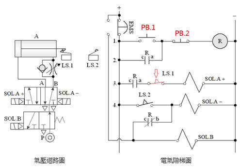
2-3-3Ё@Double
solenoid valve control circuit
Practice
purpose: to understand the principle of operation of dual solenoid
valves.
Use
circuit:
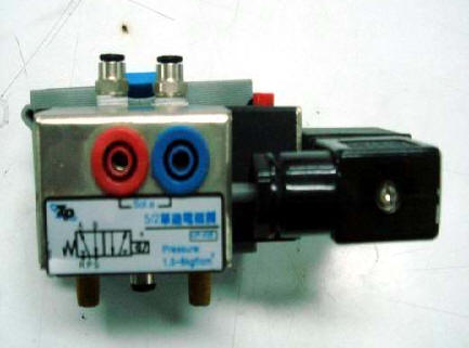
A. 5/2 double
solenoid valve
B. 5/3 neutral
double solenoid valve

C.5/3 Neutral
Air Intake Double Solenoid Valve

2-3-4Ё@series
and parallel control loop
Practice
purpose: to understand the operation principle of series and parallel
circuits.
Use
circuit:
A. Series
circuit
B. Parallel
circuit
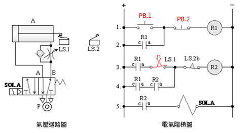
2-3-5Ё@Interlock ( Priority ) Control
Circuit
Practice
purpose: to understand the
operation principle of the interlock ( priority ) control
circuit.
Use
circuit:
2-3-6Ё@One
reciprocating control loop
Internship
purpose: understand the function of memory circuit and limit switch and
the application of automation.
Use
circuit:
A. 5/2 single
solenoid valve
B.
5/2 double
solenoid valve
2-3-7 Continuous
reciprocating control loop
Internship
purpose: understand the function of memory circuit and limit switch and
the application of automation.
Use
circuit:
A. 5/2 single
solenoid valve
B. 5/2 double
solenoid valve
2-3-8Ё@Delay
control loop
Internship
purpose: to understand the
function of Timer .
Use
circuit:
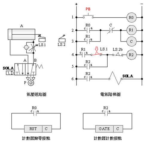
2-3-9Ё@counting
control loop
Internship
purpose: to understand the
function and application of the counter (Counter) .
Use
circuit:
2-3-10Ё@Emergency
s homing control loop
Internship
purpose: understand 5/2 emergency
s homing control.
Use
circuit:
A. Single
solenoid valve emergency s homing control

B. Single
solenoid valve returns to position after emergency s is released
C. Double
solenoid valve emergency s homing control
D. Double
solenoid valve returns after emergency s is released
2-3-11Ё@Emergency
s and move to the end control loop
Practice
purpose: to understand the function of 5/2 double
solenoid valve emergency s moving to the end control.
Use
circuit:
2-3-12Ё@Single
button ON/OFF control
circuit
Internship
purpose: to understand how to achieve the function of power switch with
a single button.
Use
circuit:
2-3-13Ё@Load
balancing control loop
Practice
Objective: Learn how to 2 Ke 5/2 single
solenoid valve with the relief valve reaches the intake bilateral
attached load balancing function.
Use
circuit:
A.
5/2 single
solenoid valve load balance control
B. 5/3 dual
solenoid valve load balance control
2-3-14 Load
lock control circuit
Practice
Objective: Learn how to 2 Ke 5/2 single
solenoid valve with bilateral guide intake valve reaches annexed locking
function.
Use
circuit:
A. 5/2 single
solenoid valve load lock control
B.
5/3 dual
solenoid valve load lock control
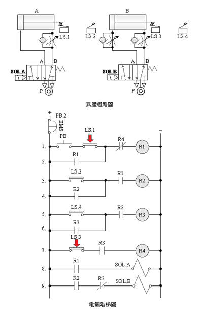
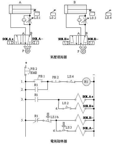
2-4-1
DoubleЁ@-cylinder
sequential action control circuit
The
purpose of the practice: to use solenoid valve with limit switch and
electrical circuit for sequential control of double pneumatic cylinders.
Use
circuit:
A.
5/2 single solenoid
valve sequence control
B. 5/2 double
solenoid valve double cylinder sequence action control
C. 5/2 single
solenoid valve double cylinder sequential action control
D. 5/2 double
solenoid valve double cylinder sequence action control
E.
5/2 single
solenoid valve double cylinder sequential action control

F.
5/2 double
solenoid valve double cylinder sequence action control
2-4-2Ё@Delay
sequence control loop
The
purpose of practice: to control the time delay sequence with double
pneumatic cylinder solenoid valve, limit switch, timer and electrical
circuit.
Use
circuit:
A. 5/2 single
solenoid valve delay control
B.
5/2 double
solenoid valve delay control
2-4-3Ё@Delayed Repeat Action
Control Circuit
The
purpose of the practice: to control the sequence of time-delayed
repetitive actions by using double pneumatic cylinders with solenoid
valves, limit switches, timers and electrical circuits.
Use
circuit:
A.
5/2 single
solenoid valve time-delay iterative control
B.
5/2 double
solenoid valve time-delay repetitive control
2-4-4Ё@Counting
sequence control loop
The
purpose of the practice: to control the sequence of time-delayed
repetitive actions by using double pneumatic cylinders with solenoid
valves, limit switches, timers and electrical circuits.
Use
circuit:
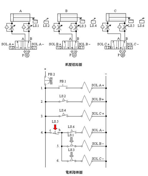
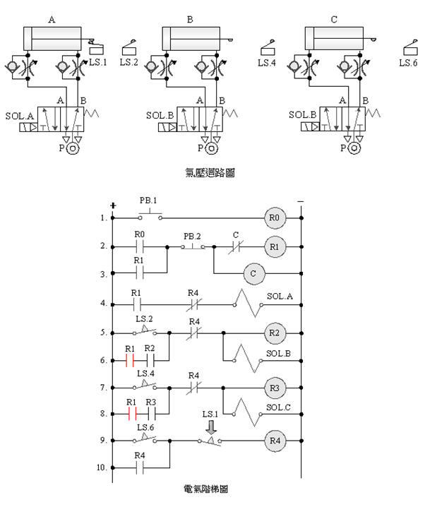
2-4-5 single
solenoid valve three-cylinder sequence action, delay, emergency return
loop
The
purpose of the practice: to use three pneumatic cylinders with 5/2 single
solenoid valve, limit switch, timer and EMS emergency
s button for sequential action, delay and emergency return control.
Use
circuit:
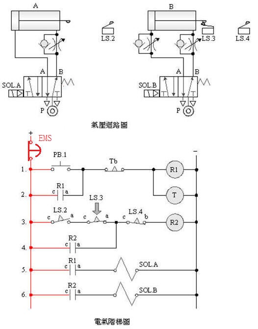
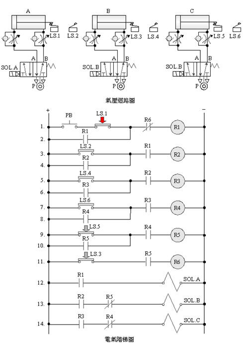
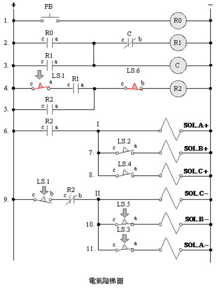
2-4-6Ё@Double
solenoid valve triple cylinder sequence action reverse sequence return
circuit after emergency s
Internship
purpose: Use three pneumatic cylinders with 5/2 double
solenoid valves, limit switches and EMS emergency
s buttons to do sequential actions and reverse sequence return control
after emergency s.
Use
circuit:
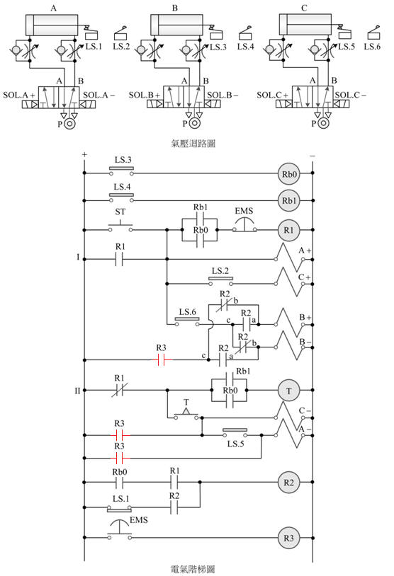
2-4-7Ё@Single
solenoid valve three-cylinder sequence action emergency s return circuit
The
purpose of practice: To control
the sequence delay action with three pneumatic cylinders
with 5/2 single
solenoid valve, limit switch and electrical circuit.
Use
circuit:
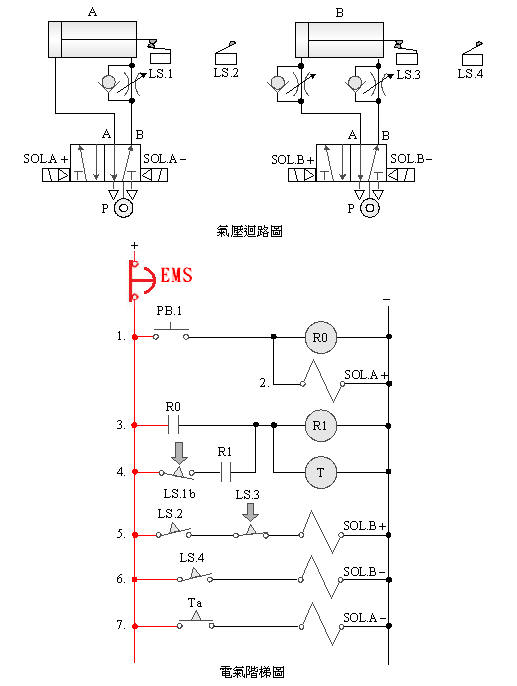
2-4-8 Double
solenoid valve triple cylinder sequence action emergency s stroke to the
end to continue action control circuit
The
purpose of the practice: Use three pneumatic cylinders with 5/2 double
solenoid valves, limit switches, and electrical circuits for sequential
actions to continue the action control after the emergency s stroke is
released to the end.
Use
circuit:
2-4-9Ё@Single
solenoid valve three-cylinder sequence action emergency s synchronous
homing control loop
The
purpose of the practice: use three pneumatic cylinders with 5/2 single
solenoid valve, limit switch and electrical circuit for emergency s
synchronous return control.
Use
circuit:
2-4-10 double
solenoid valve three cylinder timing control circuit
The
purpose of the practice: use three pneumatic cylinders with 5/2 double
solenoid valves, limit switches, timers and electrical circuits for
timing control.
Use
circuit:
2-4-11Ё@Single
solenoid valve three-cylinder sequential action circuit
The
purpose of the practice: to control
the sequence action with three pneumatic cylinders with 5/2 single
solenoid valve, limit switch and electrical circuit.
Use
circuit:
2-4-12Ё@double
solenoid valve three cylinder counting control loop
The
purpose of practice: to use three pneumatic cylinders with 5/2 double
solenoid valves, limit switches, counters and electrical circuits for
counting control.
Use
circuit:
2-4-13Ё@Single
solenoid valve three cylinder counting sequence action circuit
The
purpose of the practice: To control
the sequence counting action with three pneumatic cylinders
with 5/2 single
solenoid valve, limit switch, counter and electrical circuit.
Use
circuit:
Ё@
2-4-14Ё@three-cylinder
two-stage non-return action circuit
The
purpose of the practice: Two-stage
non-return sequence action control with three pneumatic
cylinders with 5/2 single
solenoid valve, limit switch and electrical circuit.
Use
circuit:

[1] Relation
between switching signal and touch: the
touch and signal switching
relationship between the pneumatic
cylinder and the roller valve during the movement stroke.
Taking A+B+B - A - as
an example, the diagram of the relationship between the switching signal
and the touch is as follows:
Ё@
[2] Displacement - time
graph: A graph
indicating the action state of the pneumatic cylinder. In the figure,
the horizontal axis is time, the vertical axis is displacement, and the
slope is speed.
Take Aslow+B+tB - A - as
an example, the B cylinder
is slow out and fast back, and the displacement - time
diagram is as follows:
Ё@
 Ё@
Ё@