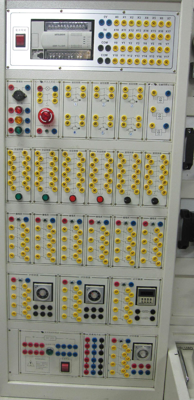
Electric hydraulic control is based on the hydraulic control circuit through solenoid valves, pressure switches and other electrical and hydraulic conversion components and limit switches, Magnetic reed switches and other position sensing components, and the electrical control circuit is used to control hydraulic direction, pressure, flow, etc. to facilitate control The electrical system is used for hydraulic control with high output, and some high-cost and heavy hydraulic control components are replaced with low-cost electronic control components. Although it needs to be assembled with hydraulic circuit and electric control circuit, it can achieve more economical cost, more convenient operation, more flexible composition and more diversified functions.
5-1.1 Control signal
The control signal has different requirements depending on whether the controlled component has a reset function. Most controlled components with a reset function are equipped with a return spring. Therefore, when the control signal is eliminated, the controlled component will return to the initial state, so the control signal must continue Exist , this kind of signal is called standing wave signal ; the controlled element without reset function, the controlled element will maintain the state after control when the control signal is eliminated, until the reverse control signal is generated, this kind of controlled element has Similar to the characteristics of memory, the control signal can be turned off after the controlled element is switched . This signal method is called pulse signal .
¡@
5-1.2 Hydraulic solenoid directional control valve
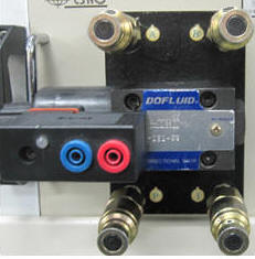
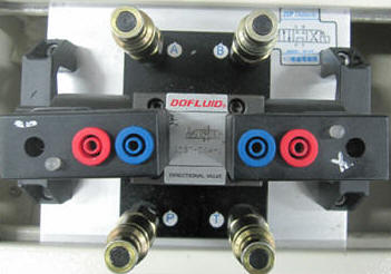
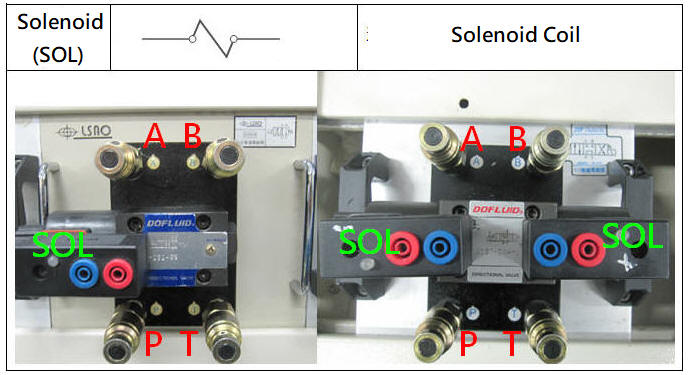
Hydraulic directional control valve is a solenoid current signal is switched to the direction of flow of the hydraulic pressure in the hydraulic cylinder built into, or back and forward rotation of the cylinder of the hydraulic motor, the control of the inversion, the common electromagnetic control valve with a 110VAC , 220VAC , 24VDC of The voltage specification is divided into single solenoid valve and double solenoid valve.
¡@
¡@
5-1.3 Hydraulic pressure switch and Magnetic reed switch
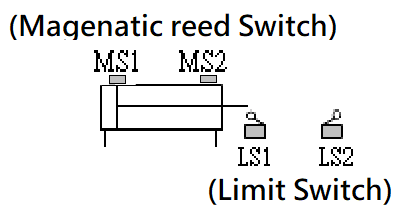
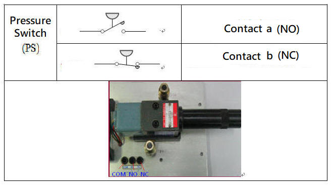
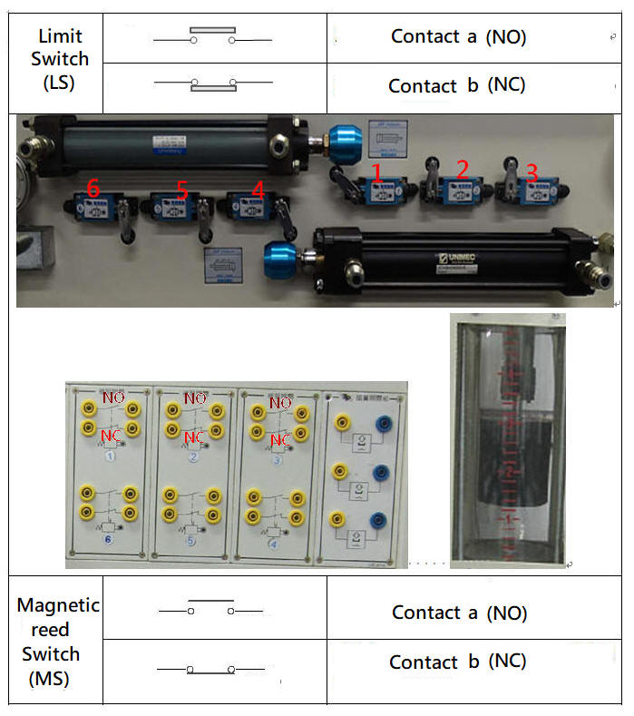
The hydraulic pressure switch is a hydraulic pressure sensing element. When the hydraulic pressure exceeds the pressure setting value of the pressure switch, the contact point of the pressure switch will switch. It is often used with solenoid valves for pressure relief or signal switching in the hydraulic system. The limit switch is a position sensing element, which is often installed in the stroke of the hydraulic cylinder. If the limit switch is not suitable for installation in the stroke, the Magnetic reed switch can be installed on the cylinder barrel of the hydraulic cylinder with a magnetized piston.
¡@
¡@
¡@
When the hydraulic pressure is started, the discharge valve adjustment bolt should be loosened to make the system setting pressure zero before turning on the motor power of the hydraulic pump. After the hydraulic pump is running, the discharge valve adjustment bolt should be gradually tightened to gradually increase the system setting pressure. When the hydraulic pump is turned off, the adjustment bolt of the relief valve should be loosened first to make the pressure drop to zero before turning off the power of the hydraulic pump.
If the installation position of the relief valve is not easy to adjust ( for example, installed in the fuselage ) , or to avoid frequent pressure changes due to loose or tightened normal adjustment, one or two-port two-position normally open solenoid valve can be installed in the pressure source and return. Between the oil ends, when the hydraulic pump is started, the solenoid valve is in the open state, so that the pressure end P and the oil return end T are connected and discharged. After the hydraulic pump starts to rotate under zero load, the solenoid valve is energized and cut off PT. The oil return passage makes the pressure rise to the system pressure set by the relief valve.
¡@
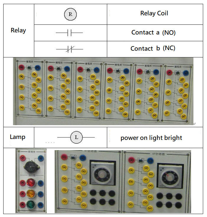
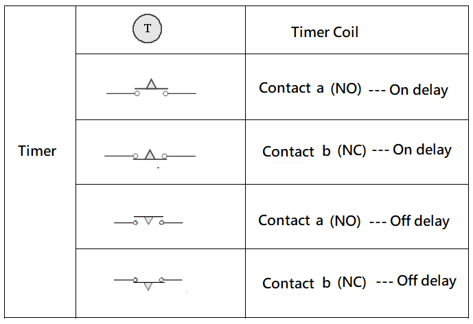
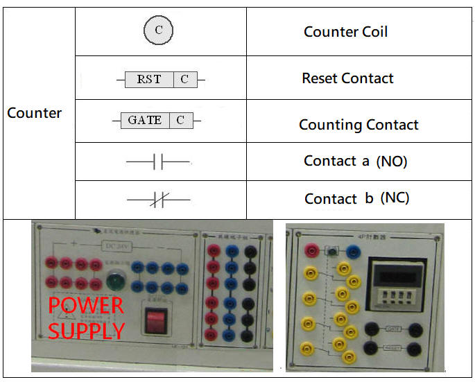
5 -1.5 Electrical components commonly used in electric hydraulic control
¡@
¡@
¡@
¡@
?
1. When wiring, make sure to turn off the power to avoid electric shock.
2. Hold the connector end when connecting or disconnecting wires , and do not pull the wires to avoid damage to the internal copper wires.
3. When wiring, you should follow the order of the ladder diagram from left to right, up and down , and do not jump at will to avoid inaccurate wiring and increase trouble.
4. When starting the hydraulic pump, the relief valve ( overflow valve ) should be loosened first . Under no load, start the hydraulic pump. The pressure should be zero at this time. Then gradually tighten the relief valve and adjust the pressure to the required level. Operating pressure ( low pressure pump 35kgf/cm 2 is about 500 psi , high pressure pump 55kgf/cm 2 is about 800 psi) .
5. Take the tube when both hands pipe , rendering the joint impact machine or ground, and hydraulic pipes should pay attention not to fall, so as to avoid deformation of the joint damage. When connecting or disassembling hydraulic pipes, hold the sleeve of the pipe end with one hand and hold the pipe with the other hand. Take the pipe vertically and remove the pipe. Do not plug or pull strongly to avoid damage to the joint.
6. Should pay attention to whether the amount of oil is sufficient? Is the oil temperature and oil pressure too high ( do not exceed 80 ¢J and 60Kgf/cm 2 ) ?
7. After the hydraulic and electrical circuits are connected properly, turn on the pressure source and the circuit switch to start the circuit.
8. If there is no power supply after power-on, check whether the power supply is normal or whether there is a short-circuit phenomenon? If the power supply is normal, turn off the power switch first, and then restart the power supply after removing the cause of the obstacle.
9. When the same contact is reused in the circuit, separate wiring and avoid sharing as much as possible to reduce the chance of short circuit and error signal generation.
10. The hydraulic pipes and component joints should be removed after the pressure is completely relieved to avoid pressure remaining in the pipeline and valve body. When piping, if there is residual pressure in the joint and the non-return joint cannot be opened, you can try to cut the directional valve that has been taken over to reduce pressure, or use a wrench to loosen the joint and release the pressure before taking over.
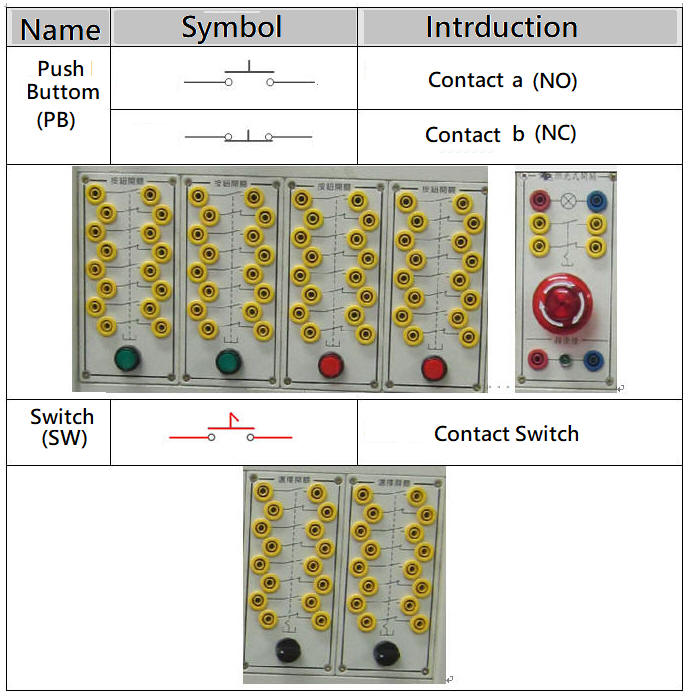
11. The NO. (Normally Open) normally open contact is the a contact ( usually it is open and not energized, after switching it becomes a closed circuit ) , the NC (Normally Closed) normally closed contact is the b contact ( usually a closed circuit is energized) , After switching, it becomes an open circuit and no power ) .
12. After all operations are completed, the hydraulic source and power supply should be turned off , all pressure settings should be reduced to the minimum, the hydraulic cylinder should be returned to the position, the residual pressure in the pipeline and components should be removed, the pipelines, valves and wires should be collected, and clean the machine and Oil stains on the ground, and fill in the use record form.
¡@
5-3-1¡@Bypass pressure relief control loop
1. The purpose of the practice: to understand the control function of the bypass pressure relief of the hydraulic pump.
2. Use loop:

¡@
5-3-2¡@Single solenoid valve direction control loop
1. The purpose of practice: to understand the function of 4/2 single solenoid valve direction control.
2. Use loop:

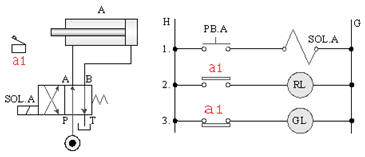
5-3-3¡@Limit switch switching characteristics control loop
1. The purpose of practice: to understand the function of limit switch contact switching.
2. Use loop:
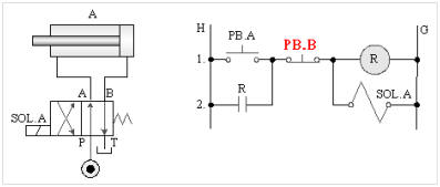
5-3-4¡@Single solenoid valve self-protection control loop
1. Internship purpose: to understand the function of 4/2 single solenoid valve with relay for self-protection control.
2. Use loop:
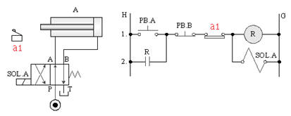
5-3-5¡@Single solenoid valve reciprocating control loop
1. The purpose of practice: to understand the function of 4/2 single solenoid valve with relay and limit switch for one reciprocating control.
2. Use loop:
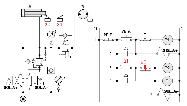
5-3-6¡@Single solenoid valve timing control loop
1. The purpose of the practice: to understand the function of 4/2 single solenoid valve with timer control.
2. Use loop:
A._Single solenoid valve timing control
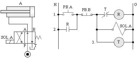
B._Single solenoid valve timing control
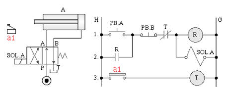
5-3-7¡@Single solenoid valve continuous reciprocating control loop
1. The purpose of practice: to understand the function of 4/2 single solenoid valve with relay and limit switch for continuous reciprocating control.
2. Use loop:
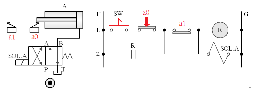
5-3-8¡@Double solenoid valve direction control loop
1. The purpose of the practice: to understand the function of the 4/3 dual solenoid valve direction control.
2. Use loop:

5-3-9¡@Double solenoid valve once reciprocating control loop
1. The purpose of practice: to understand the function of 4/3 double solenoid valve with limit switch for one reciprocating control.
2. Use loop:
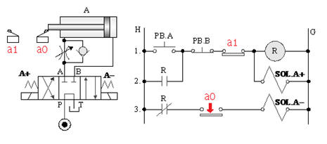
5-3-10¡@Double solenoid valve timing control loop
1. The purpose of practice: to understand the function of 4/3 double solenoid valve with timer for timing control.
2. Use loop:
A._ 4/3 dual solenoid valve timing control
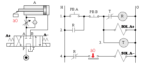
B._ 4/3 dual solenoid valve timing control
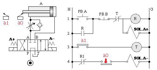
C._ 4/3 dual solenoid valve timing control
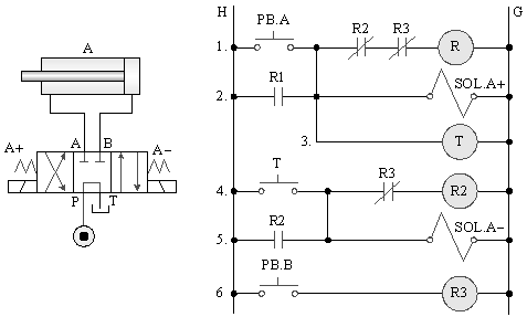
5-3-11¡@Double solenoid valve continuous reciprocating control loop
1. The purpose of practice: to understand the function of 4/3 double solenoid valve with relay and limit switch for one reciprocating control.
2. Use loop:

5-3-12¡@Counting control loop
1. The purpose of practice: to understand the function of 4/2 single solenoid valve with counter and limit switch for counting reciprocating control.
2. Use loop:

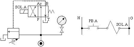
5-3-13 Load¡@Relief control loop
1. The purpose of the practice: to understand the function of the pressure relief control of the relief valve.
2. Use loop:
5-3-14¡@Speed control loop
1. The purpose of practice: to understand the function of throttle valve speed control.
2. Use loop:
A._Meter In control of hydraulic motor
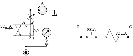
B._Meter out control of hydraulic motor

C._Bleed off control of hydraulic motor

5-3-15¡@Pressure switch control circuit
1. The purpose of the practice: to understand the function of dual solenoid valves with pressure switches for power control.
2. Use loop:
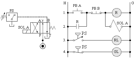
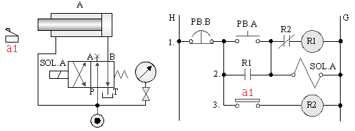
5-3-16¡@Differential cylinder control circuit
1. Practice purpose: the application of differential cylinder in differential direction control.
2. Use loop:
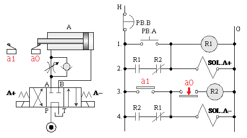
5-3-17¡@Emergencys control circuit
1. The purpose of practice: to understand the emergency s control of the reciprocating action of the double-acting cylinder.
2. Use loop:
¡@
5-4 Application circuit
¡@
5-4-1¡@Hydraulic cylinder and hydraulic motor action control circuit
1. The purpose of practice: to cooperate with the pressure switch to make the hydraulic cylinder and hydraulic motor operate in sequence.
2. Use loop:

5-4-2¡@Throttle valve control double cylinder synchronous circuit
1. The purpose of the practice: to understand the operating principle of the throttling and speed regulating synchronous circuit.
2. Use loop:
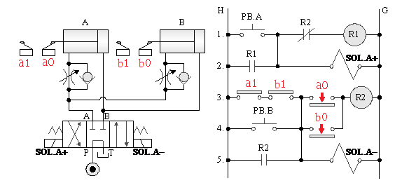
5-4-3¡@Two-stage speed control loop
1. The purpose of practice: to understand the two-stage speed control function of the 4/3 double solenoid valve circuit.
2. Use loop:

5-4-4 Counterbalance¡@valve back pressure control loop
1. Practice purpose: to understand the function of pilot counterbalance valve lifting back pressure control.
2. Use loop:
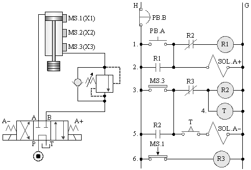
5-4-5¡@Guide check valve lock control circuit
1. The purpose of the practice: to understand the function of the guided check valve load lock control.
2. Use loop:
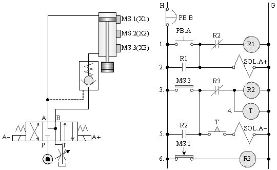
5-4-6¡@Pressure switch no load control circuit
1. The purpose of the practice: understand the application of pressure switches in no-load control.
2. Use loop:
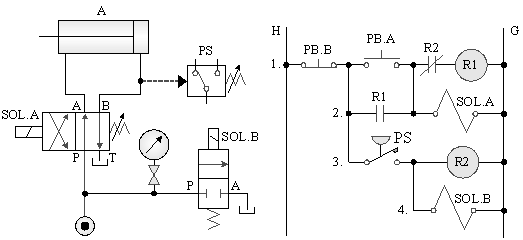
5-4-7¡@Pressure switch relief control circuit
1. Practice purpose: to understand the application of pressure switch in hydraulic pump discharge control.
2. Use loop:
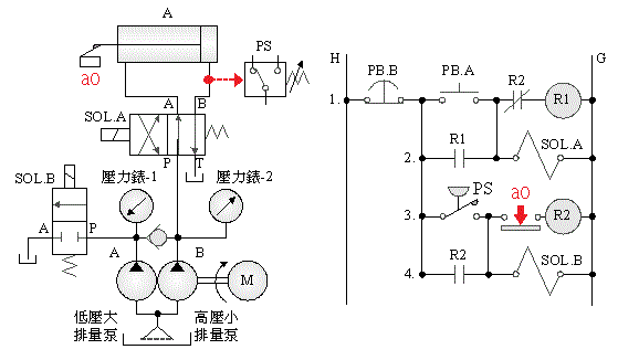
5-4-8¡@Double solenoid valve sequence control loop
1. Practice purpose: to understand the function of sequence valve for sequence control in 4/3 double solenoid valve circuit.
2. Use loop:
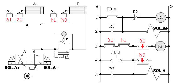
5-4-9¡@Double solenoid valve pressure reducing control circuit
1. Practice purpose: to understand the function of pressure reducing valve in 4/3 double solenoid valve circuit.
2. Use loop:
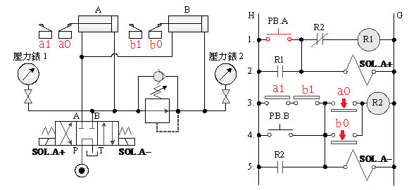
5-4-10¡@High and low pressure double pump discharge timing circuit
1. The purpose of the practice: to understand the application of 4/2 single solenoid valve in high and low pressure double pump discharge circuit.
2. Use loop:

5-4-11¡@High and low pressure double pump discharge circuit
1. Purpose of practice: To understand the application of pressure switch in high and low pressure double pump load relief circuit.
2. Use loop:

5-4-12¡@Quick return control loop
1. The purpose of the practice: to understand the application of the accumulator in the quick return of the auxiliary hydraulic cylinder.
2. Use loop:
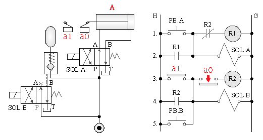
5-4-13¡@Single solenoid valve multiple reciprocating, emergency s return control loop
1. Internship purpose: to understand the function of 4/2 single solenoid valve multiple action control.
2. Use loop:

5-4-14¡@Hydraulic motor direction, speed regulation, timing control circuit
1. The purpose of the practice: to understand the application of hydraulic motor direction, speed regulation and timing control.
2. Use loop:

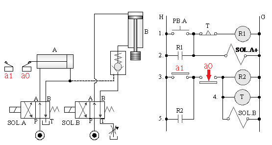
5-4-15¡@Double cylinder control circuit
1. The purpose of the practice: to understand the dual-cylinder sequence and the function of the timing control of the load lock sequence of the pilot check valve.
2. Use loop:
¡@
5-4-16¡@Differential cylinder, hydraulic motor control circuit
1. Internship purpose: to understand the application of differential, load release, and sequence control.
2. Use loop:
Annotation¡G
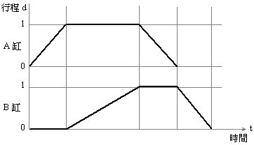
Time - stroke graph: A graph indicating the action status of the air cylinder. In the figure, the horizontal axis is time, the vertical axis is stroke, and the slope is speed. A to A + Bslow + A - B - for example, the B -cylinder back to slow the fast, time - stroke legend is as follows:
