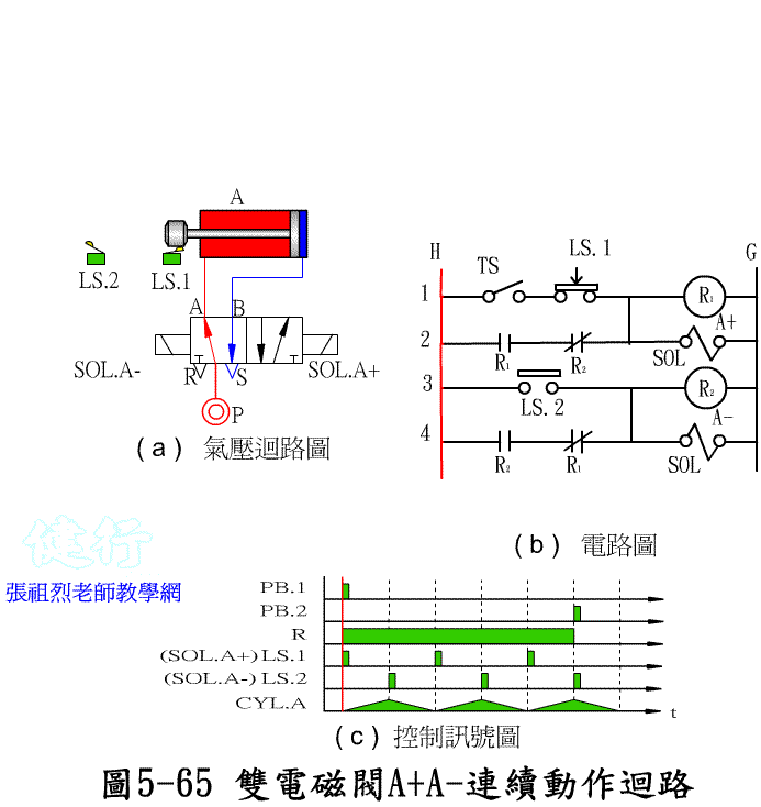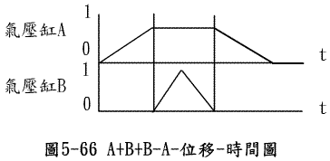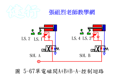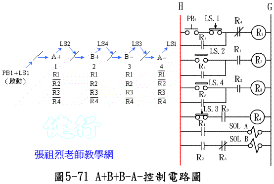
Chapter 5 Electrical-Pneumatic Control
Goto Zulie teacher teaching network Pneumatic hydraulic control practice
5-1 Electrical control element P193
5-1-1 Electrical switch (Electrical Switch) P194
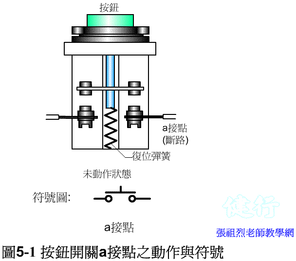
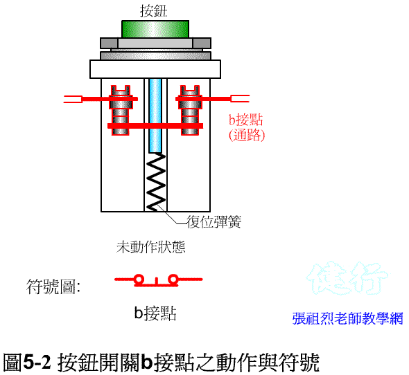
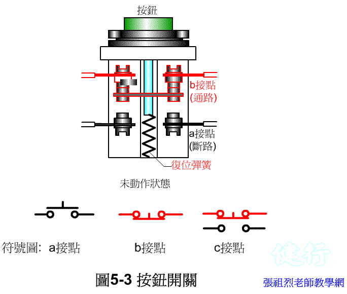
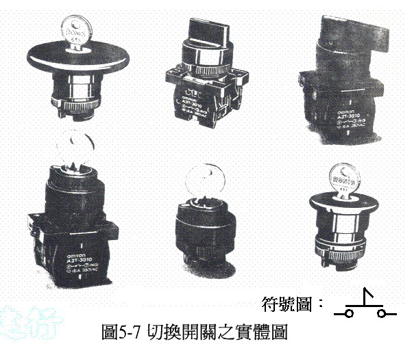
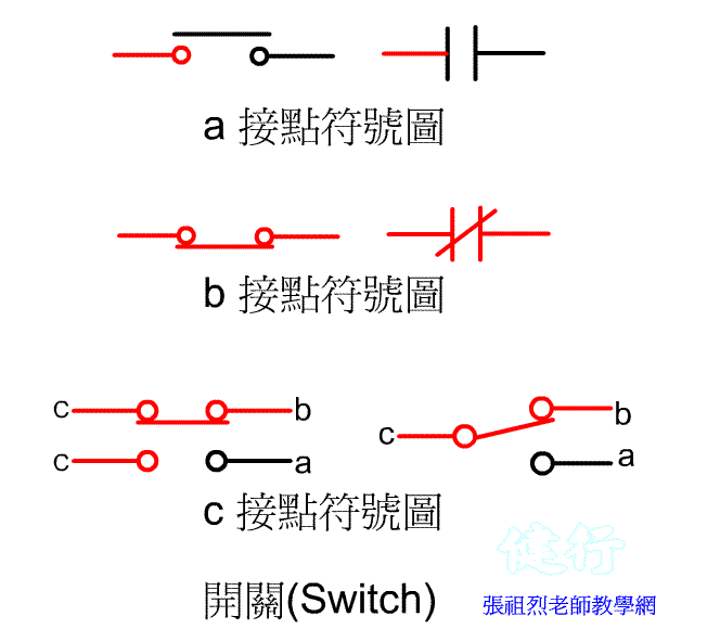
There are three types of switch contacts: “ a” contact, “ b” contact, and “ c” contact.
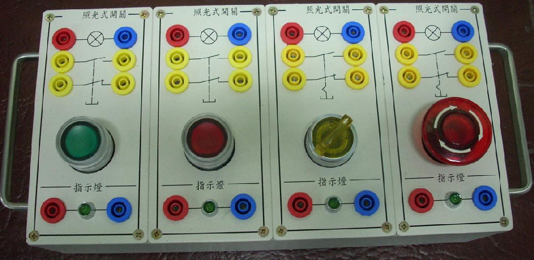
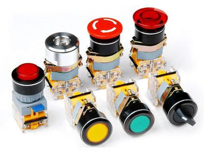
5-1-2 the Push-the Button Switch, PB P 194 the
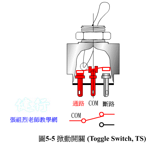
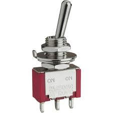
5-1-3 the Toggle Switch, TS) P197 the
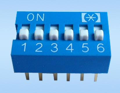
Tilt (DIP) switch DIP switch
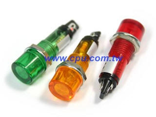
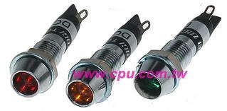
5-1-5 Pilot Lamp P199 the
Is
generally more commonly used indicator color: (1) Red :indicates
the machine is in operation;(2) Green :indicates
the machine s condition;(3) White:Indicates
power ;(4) yellow :
warning indication, fault.
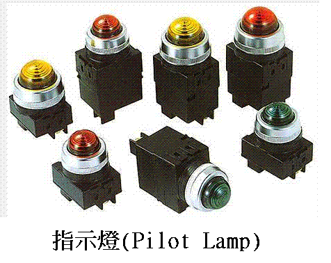
https://hyauto.en.ec21.com/Pilot_lamp--557655_557717.html
5-1-6 Sensor P199
The most commonly used sensors for sequence control
n 1. Limit Switch (LS) .
n 2. Photoelectric Switch (PHS) .
n 3. Proximity Switch (PXS) .
n 4. Pressure switch (PS)
5-1-7 Limit Switches (LS) P200 the
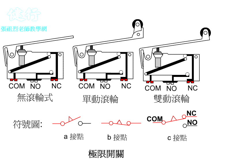
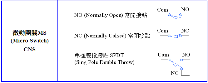
The limit switch has NO normally open contact ( ie a contact ) , and NC normally closed contact (ie b contact ) and the common point (Com) . When the limit switch is not pressed, the Com point is connected to the NC contact. When pressed, the Com and NO contacts are closed.
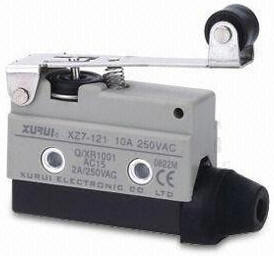
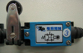
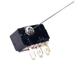
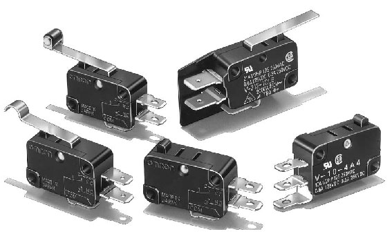
5-1-8 Micro Switch (MS) P202 the
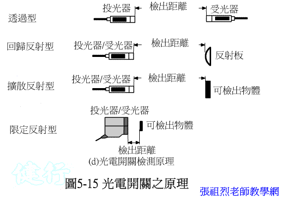
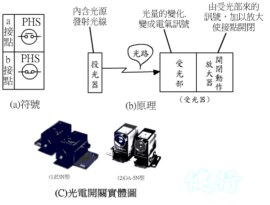
5-1-9 Photoelectric Switch (PHS) P202
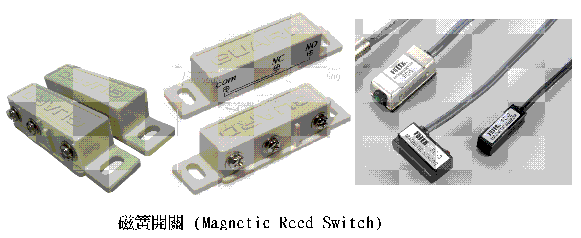
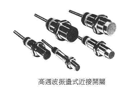
5-1-10 Proximity Switch (PXS) the P205 the
5-1-11 Pressure Switch (PS) P207
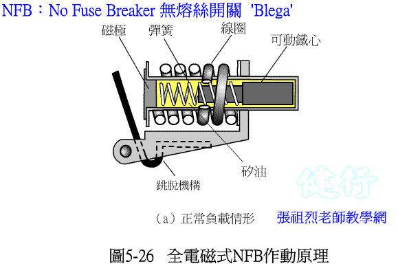
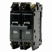
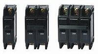
5-1-12 No Fuse Breaker (NFB) P207 the
5-2 Electromagnetic Relay and Rlectromagnetic Contactor P210
5-2-1 Principle
of Electromagnetic Relay
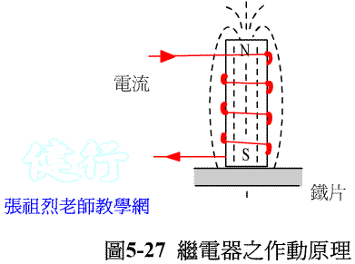
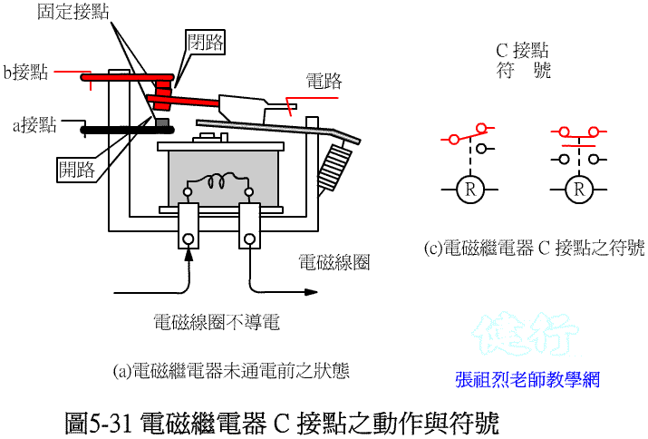
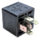
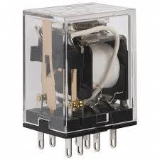
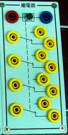
Physical diagram of Electromagnetic Relay
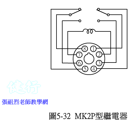
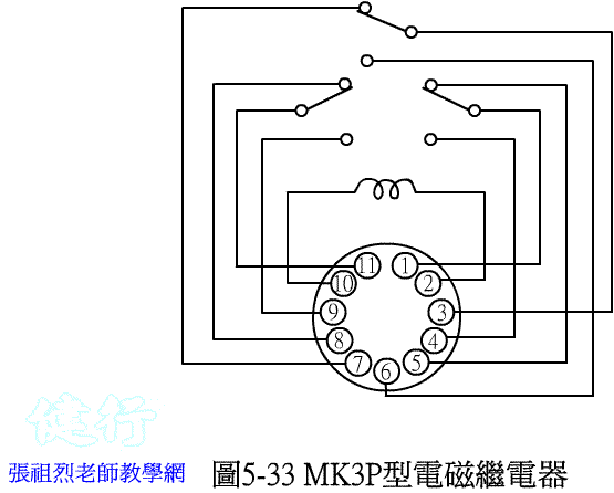
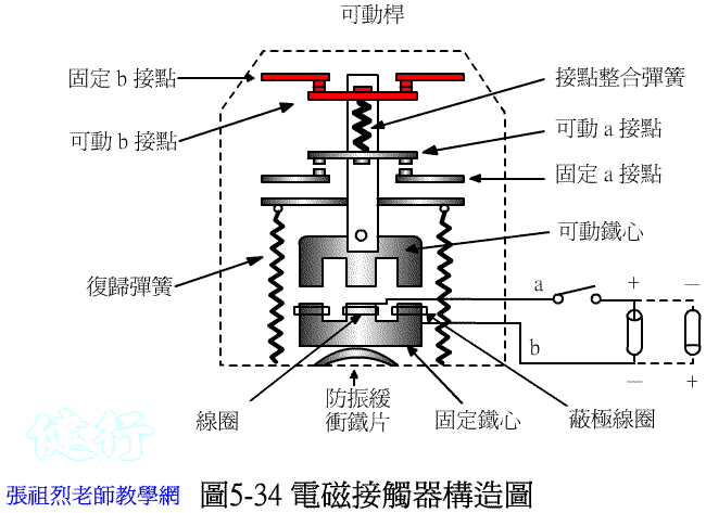
5-2-4 Electromagnetic Magnetic Contactor (MC) P216 the
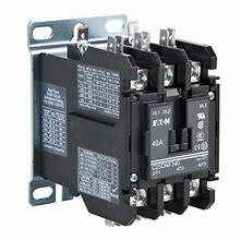
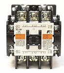
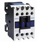
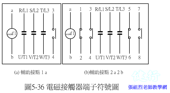
5-2-5 Thermal Relay (TH) P218 the
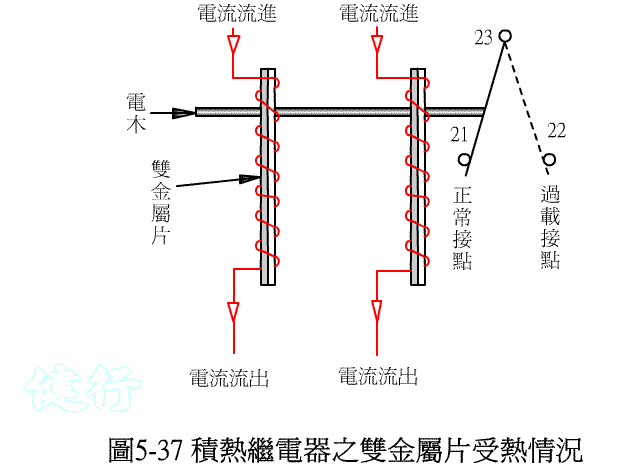
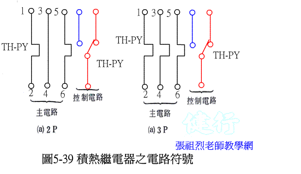
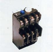
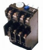
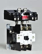
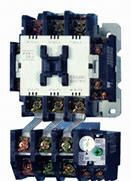
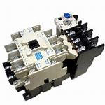
5-2-6 Magnetic switch (MS) the
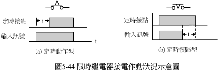
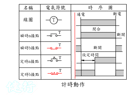
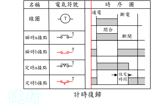
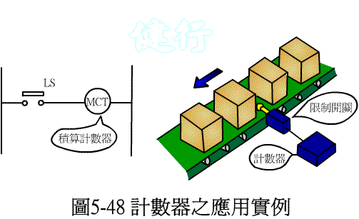
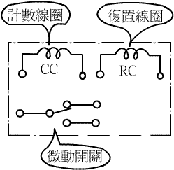
5-5 COUNTER P223
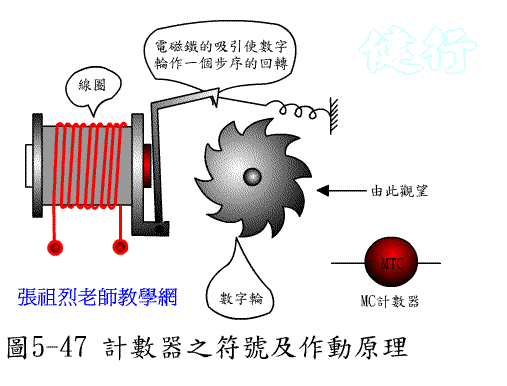
5-6 Basic logic circuit with contacts P225
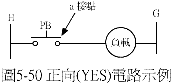
(1) YES
circuit ( Normal
phase circuit )
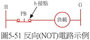
(2) NOT circuit ( Inverting circuit ) P226
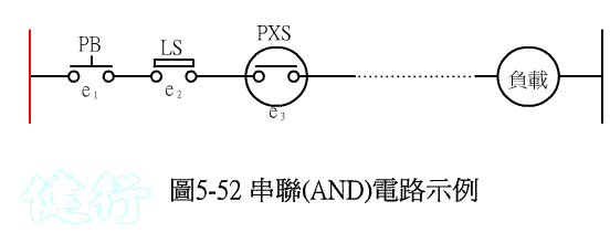
(3) AND circuit ( Series circuit ) P226
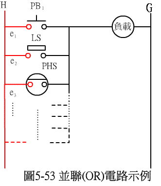
(4) OR circuit ( Oarallel circuit ) P226
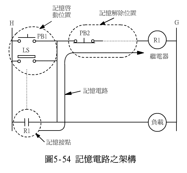
(5) Self-keep ( memory ) circuit P22 7
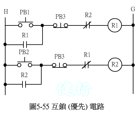
(6) Interlocking ( Priority ) circuit P227
5-7 Basic Electrical - Pneumatic Control Circuit P229
5-7-1 Control the forward and backward movement of the pneumatic cylinder by manual button
(1) Design
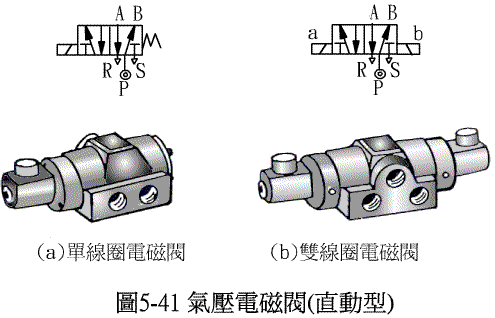
with single coil Solenoid valve P229
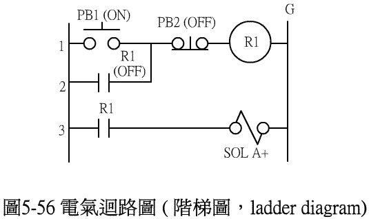
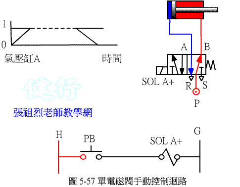
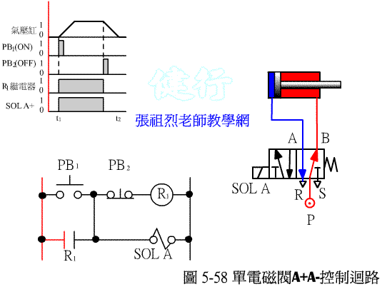
(2) design with double coil solenoid valve P231
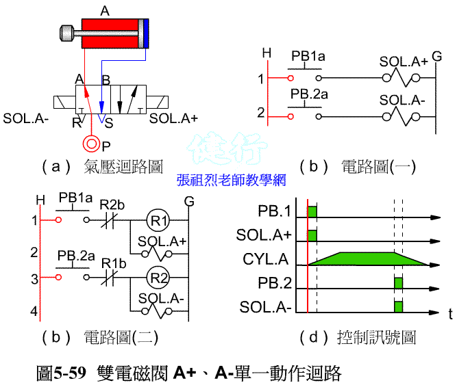
5-7-2 Forward and backward movement of pneumatic cylinder controlled by timer
(1) Design
with single coil solenoid valve P232
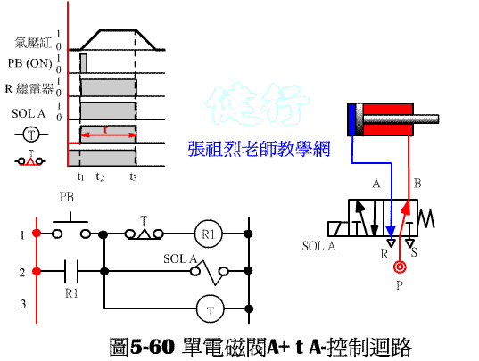
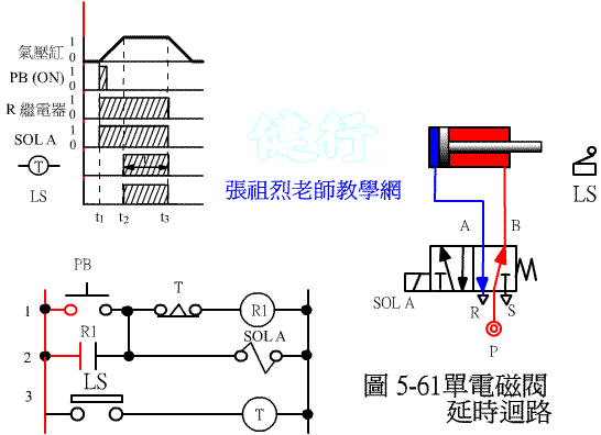
(2) design with double coil solenoid valve P236
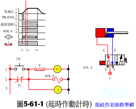
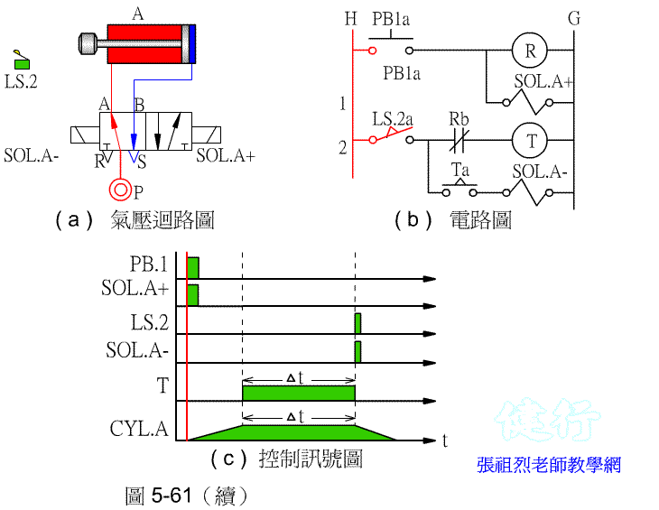
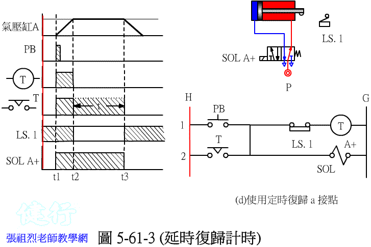
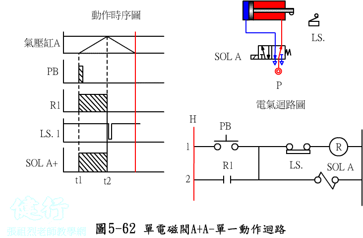
5-7-3 Automatic Forward and Backward Circuit of Pneumatic Cylinder ( Single Cycle )
(1) Design
with Single Coil Solenoid Valve P237
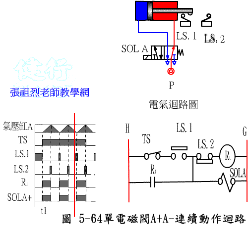
5-8 Electrical - Pneumatic
Application Circuit
P 242
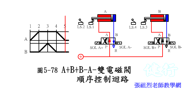
Example 5-1 Design the electrical - pneumatic circuit diagram based on the displacement time diagram:
Join auxiliary status P247
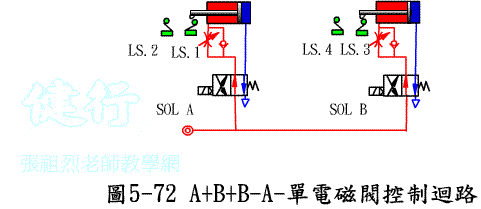
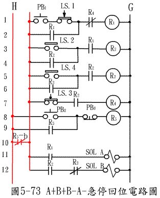
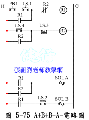
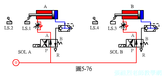
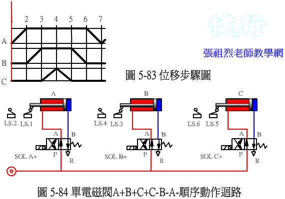
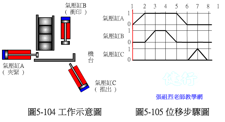
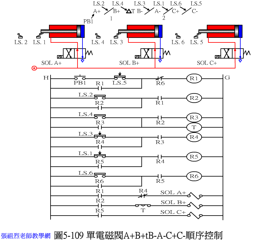
Example 5-2 Tries to design the electric - pneumatic circuit diagram based on the following displacement step diagram: P255
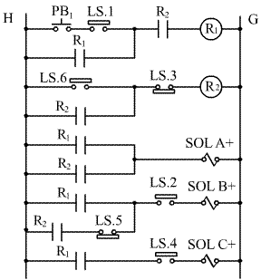
design with single coil solenoid valve
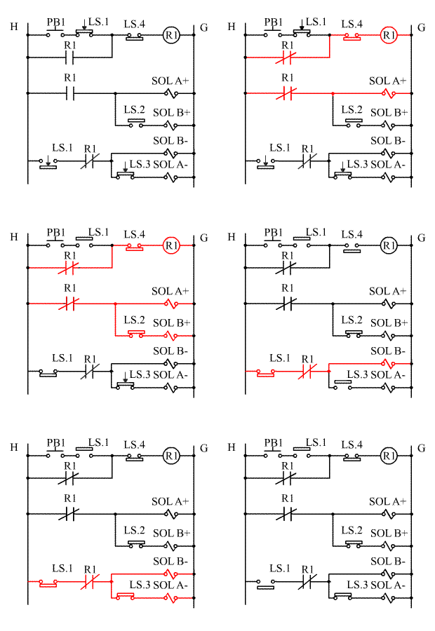
Designed with dual coil solenoid valve P262
Electrical - pneumatic control circuit design example
GOTO Chapter 6 PLC Programmable Pneumatic Pressure Control
Goto Zulie teacher teaching network Pneumatic Hydraulic control practice