Pressure control valves can be divided into the following types according to their performance:
n1. relief valve
n2. pressure Reducing Valve
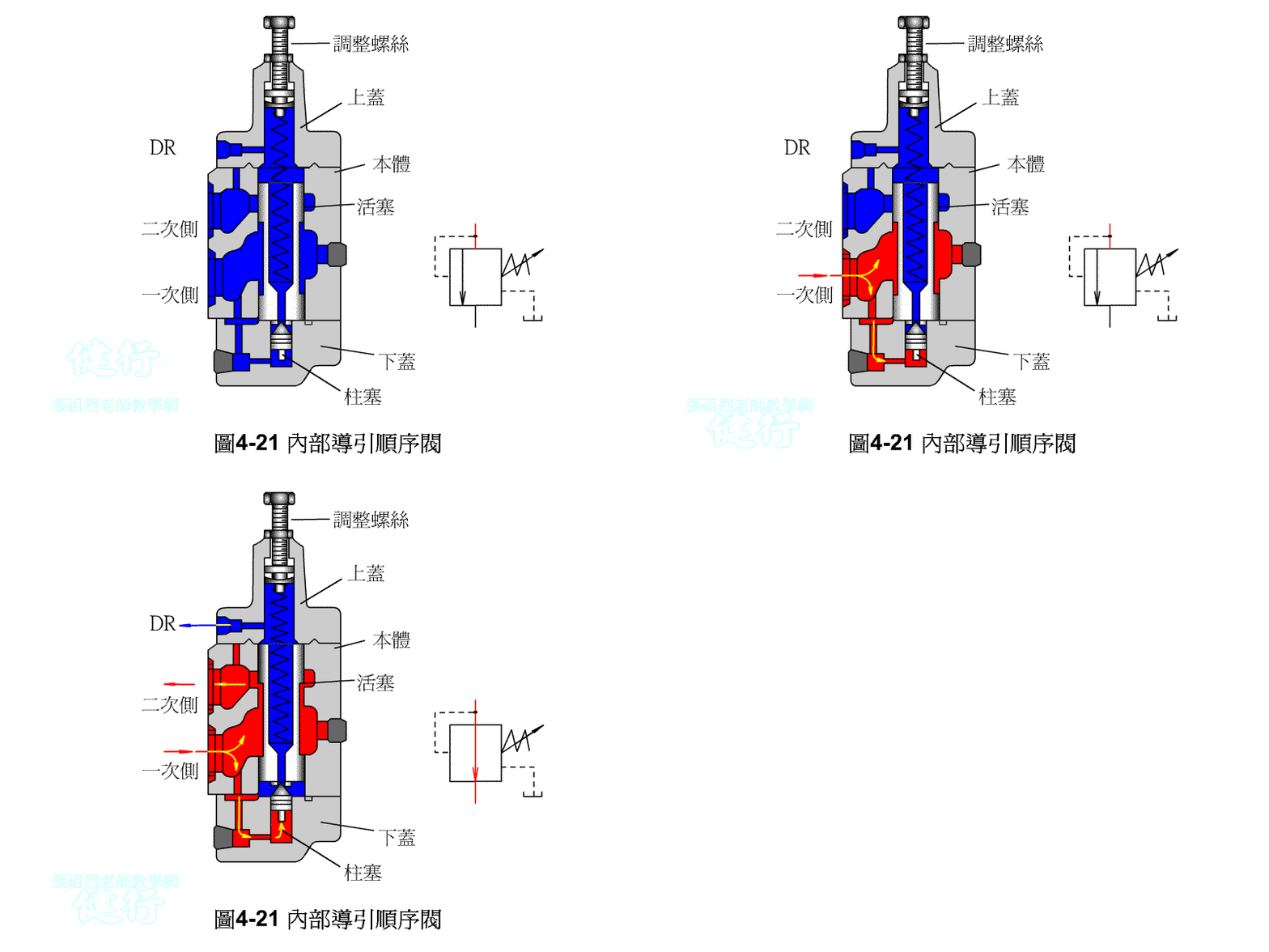
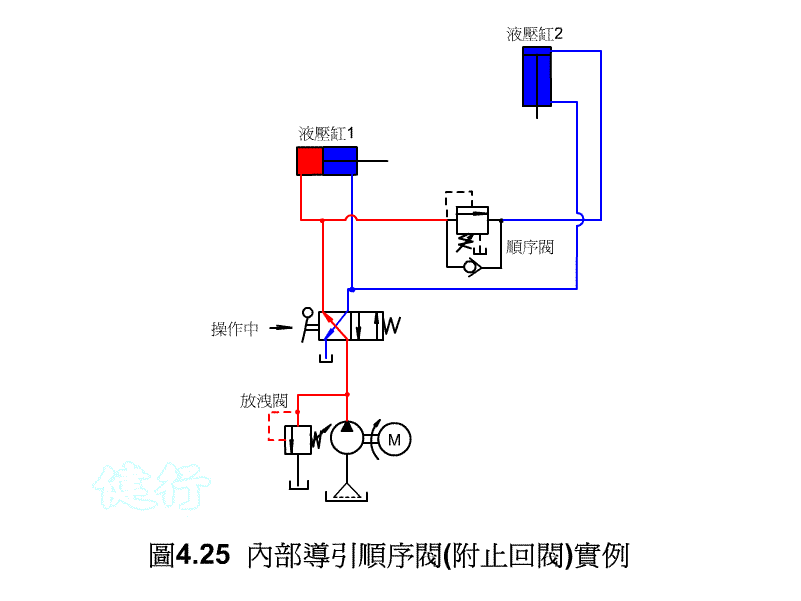
3. sequence valve
(1) relief valve
(2) unloading valve
(3) sequence valve
(4) check valve
(5) counterbalance valve
n4 booster
n5. pressure switch
=========================
4-1 RELIEF VALVE P408
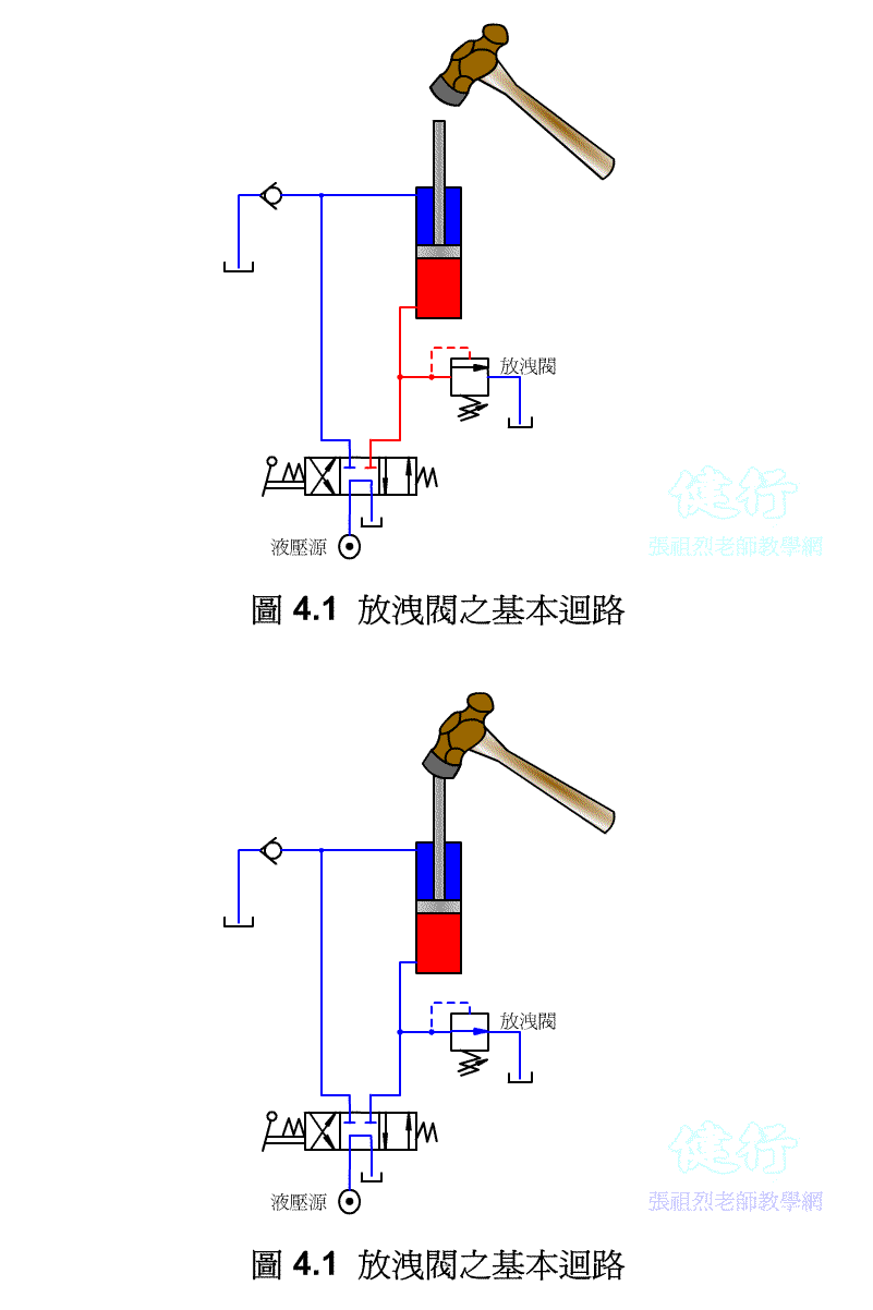
If the pressure in the circuit becomes too large due to some reasons in the hydraulic circuit, it will damage the components, so a hydraulic device needs to be set up so that when the pressure exceeds the set pressure value, part of the hydraulic oil or All are drained to the oil tank to reduce the pressure. This kind of pressure control valve is called a relief valve .
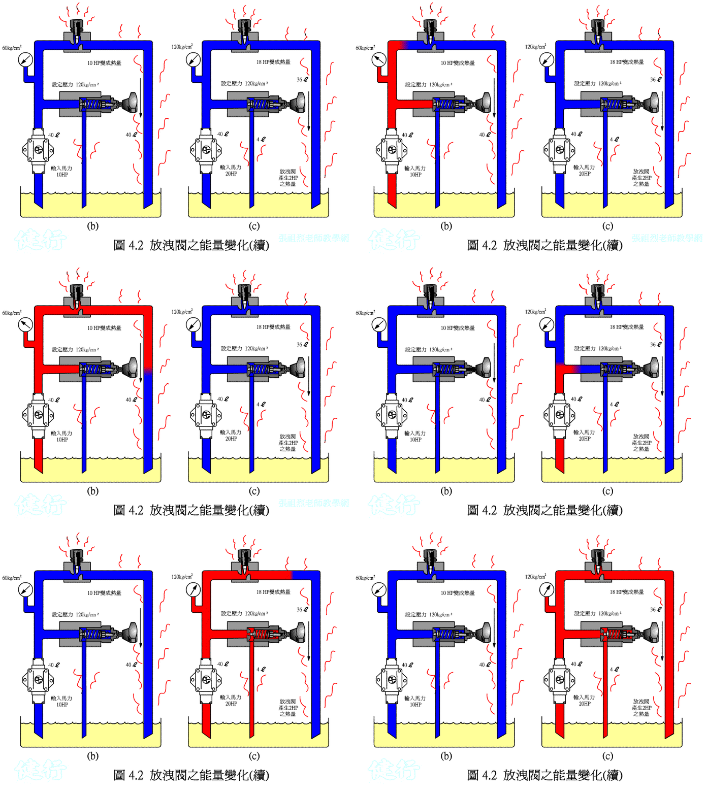
High-pressure hydraulic oil, which exceeds the set pressure of the bleed valve, partly flows back to the oil tank through the bleed valve and partly flows back to the oil tank through the flow control valve, generating a large amount of heat.
4-1-1 Operating Principle of Drain Valve P409
4-1-2 Direct Acting Relief Valve P411
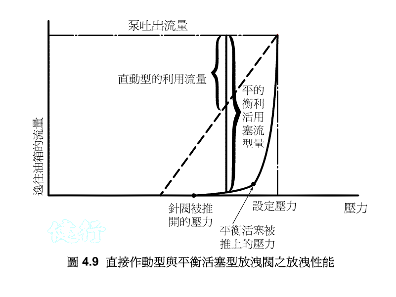
this type of relief valve has a simple and cheap structure, but when the valve stem is opened and hydraulic oil flows back to the tank, the valve stem is extremely susceptible to vibration, causing chattering such as frequent movements, and the valve seat is easily damaged. At the same time, its pressure adjustment range is limited, so it is mainly used for safety valves, remote control valves and low pressure adjustment.
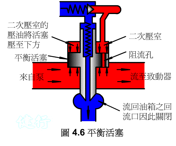
4-1-3 balance piston type discharge valve P412 Do the

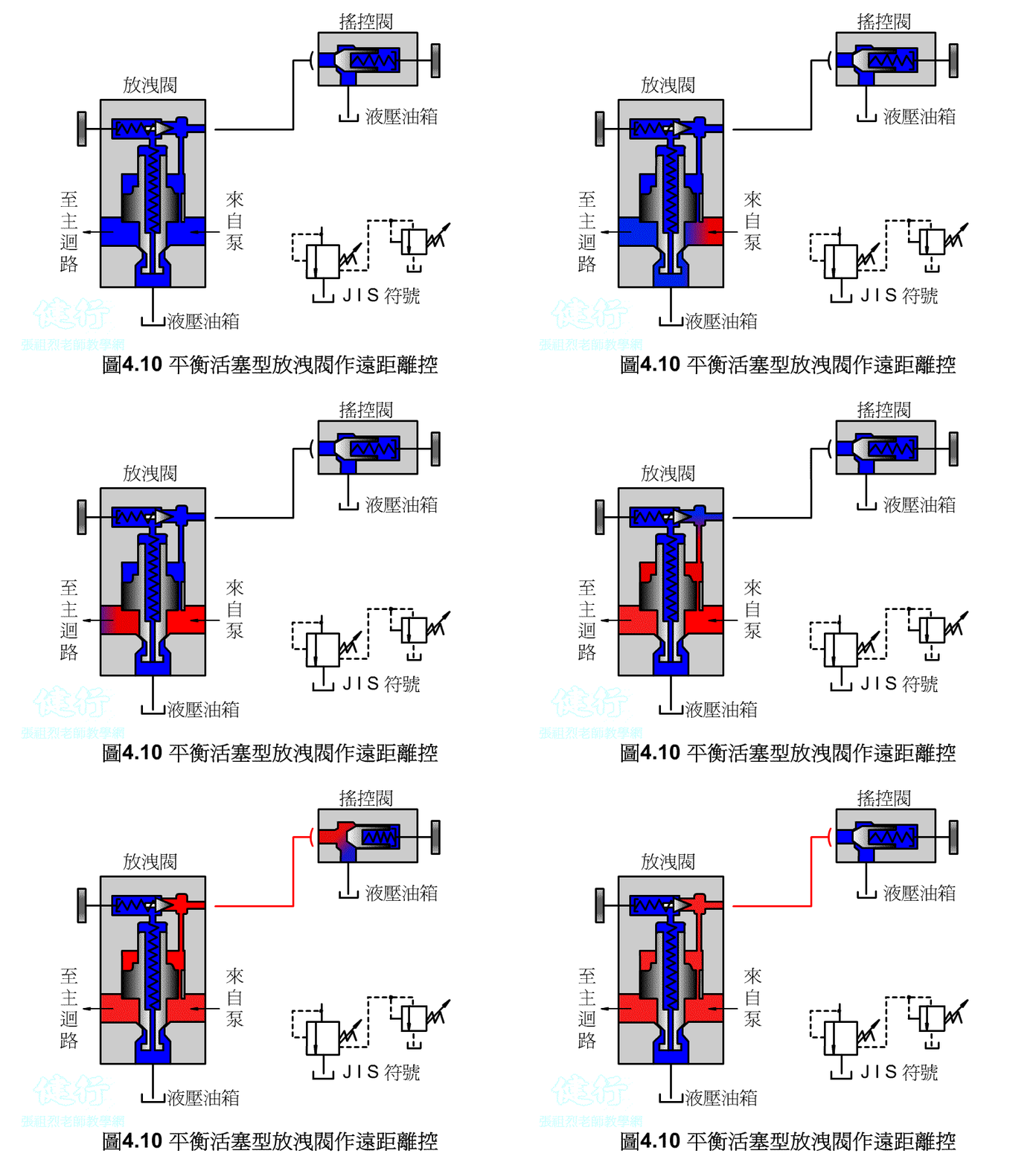
1. the Remote Control P415 the
Connect the remote control valve to the vent, the remote control valve can adjust the pressure of the main relief valve for remote control, but the set pressure of the remote control valve must be less than the set pressure of the main relief valve.
2. Unloading Control P416
In order to save power loss and prevent the rise of oil temperature, as shown in Figure 4-11 , when the solenoid valve (a) is not energized, the hydraulic oil in the vent port directly flows back to the oil tank, and the main valve is fully opened to make the pump run without load. If the solenoid valve (a) is energized and energized, the main valve will return to its position and the relief valve will begin to discharge the set pressure.
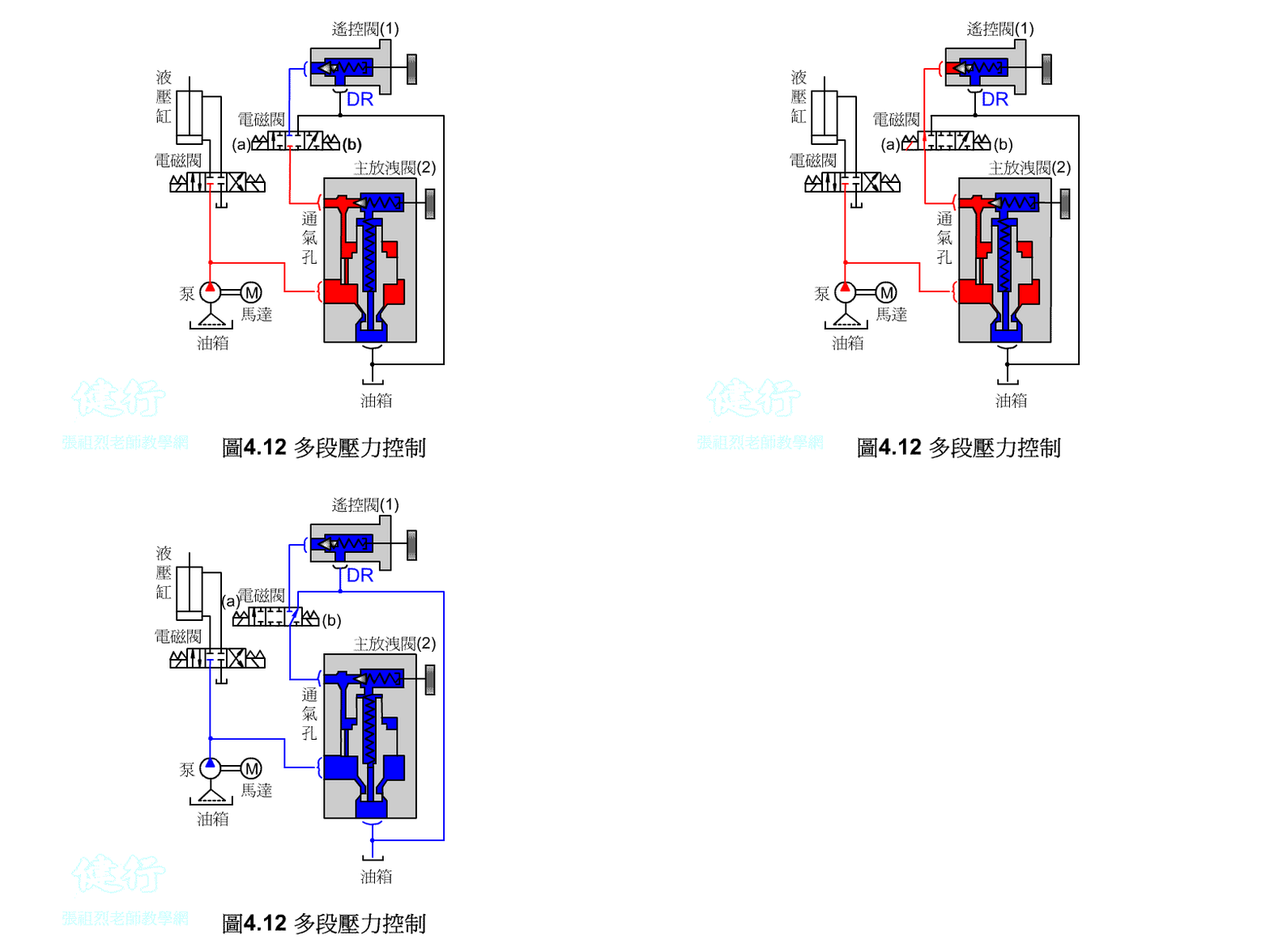
3. Multi-pressure Control P416
3/3 solenoid valve operation, when in the neutral position, the system pressure will become the set pressure of the main relief valve (2) .
n When the 3/3 solenoid valve is switched to (a) position, the system pressure will become the set pressure of the remote control valve (1) .
n When the 3/3 solenoid valve is switched to the (b) position, the system pressure will become unloaded by the main relief valve (2) .
4-2 REDUCING VALVE P417
( 1 ) The role of pressure reducing valve
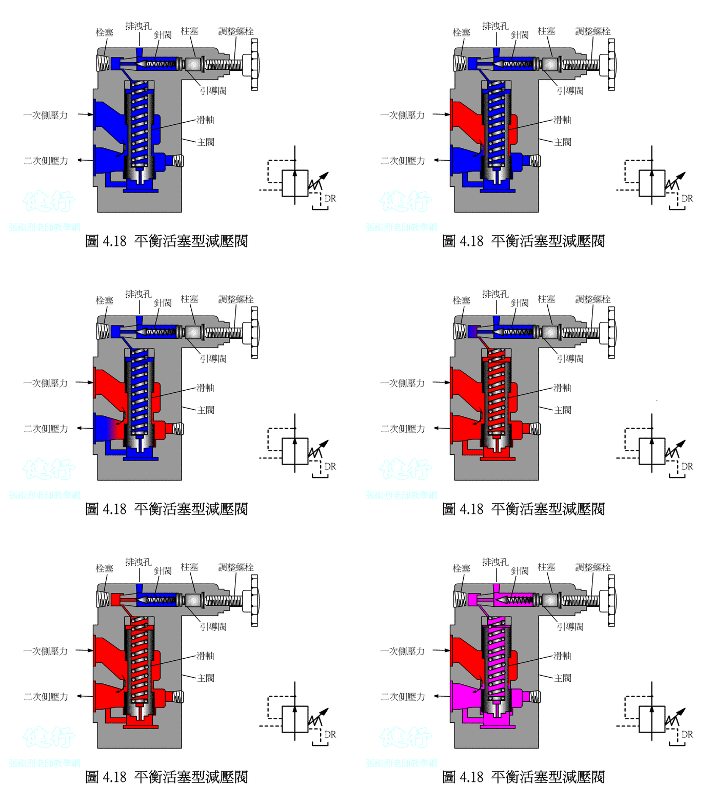
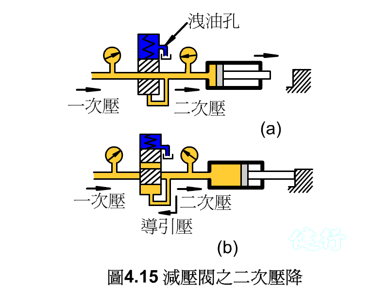
The pressure reducing valve is very similar to the drain valve, but its function is completely opposite. The drain valve flows excess oil back to the tank in order to control the IN side ( primary pressure side ) . The pressure reducing valve is used to control the pressure on the OUT side ( secondary pressure side ) and prevent excess hydraulic oil from passing through.
( 2 ) What is decompression P418
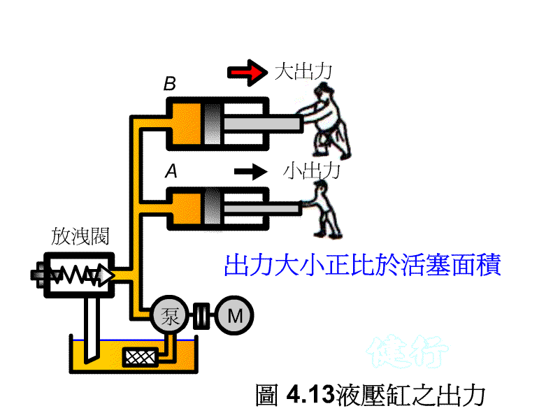
F = PA, so if you want to change the output of the hydraulic cylinder, you can:
1. Change the piston area
2. Change the pressure
( 3 ) Why the secondary pressure can maintain a certain level P419

4-2-1 Direct Acting Reducing Valve P419 the
4-2-2 balance piston-type valve P420
4-2-3 Application Example of Pressure Reducing Valve P422

 \
\
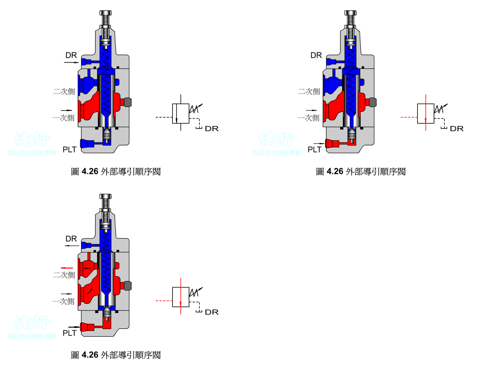
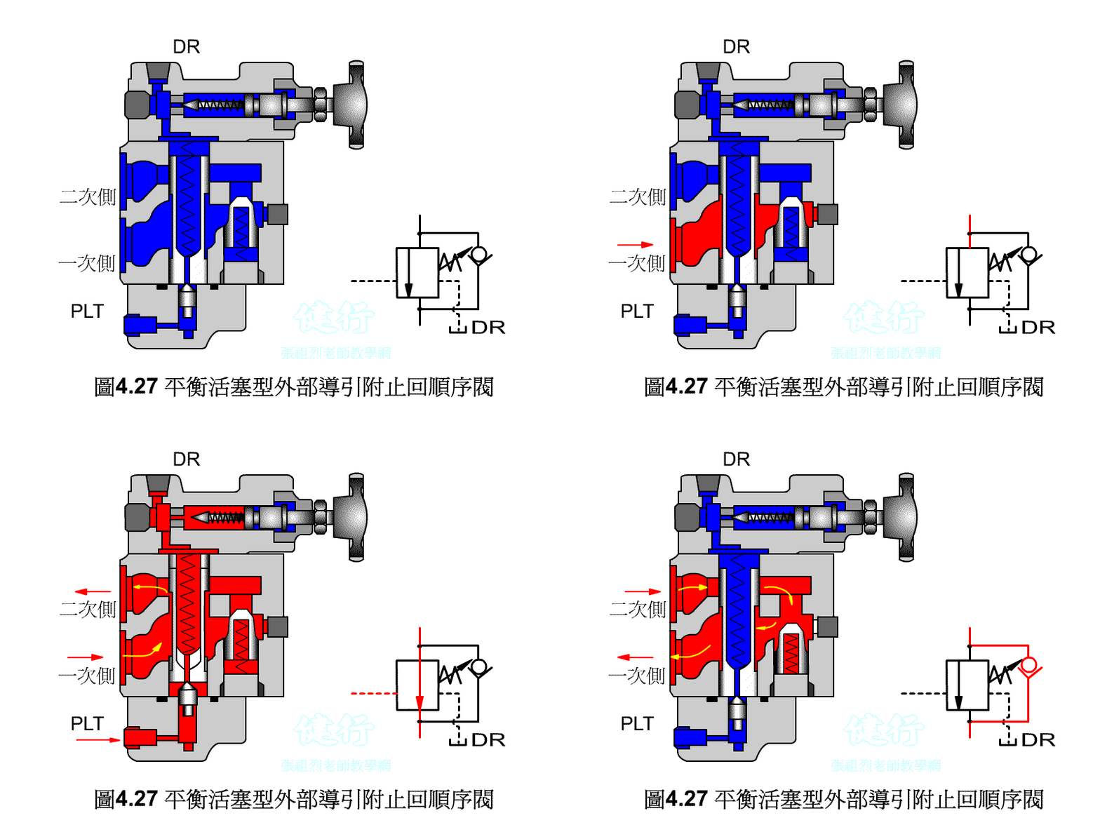
An outer portion of the sequence valve guide P426 the
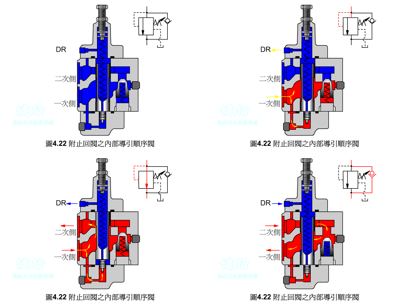
Attached backs outer portion guide sequence valve P426 the
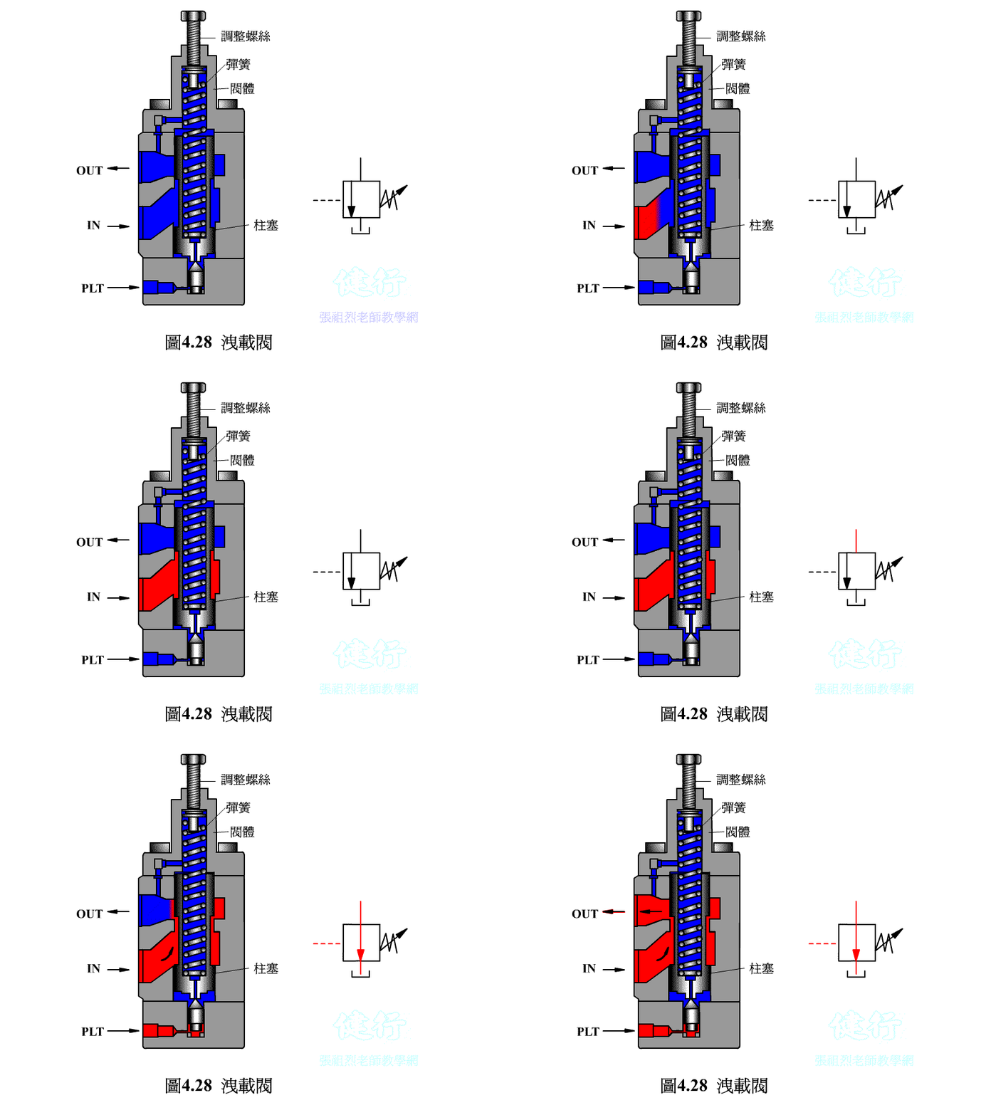
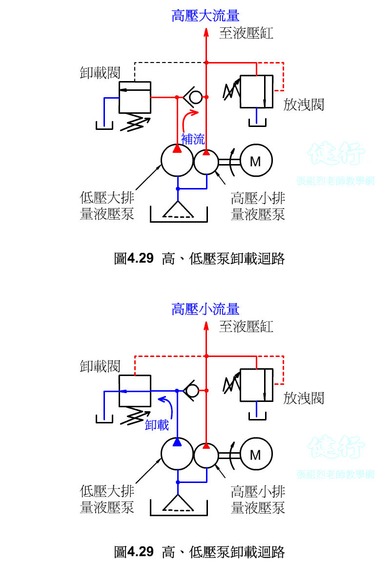
4-3-2 Unloading valve P426 the
If the hydraulic pump uses a fixed displacement type, when hydraulic oil is temporarily not needed in the hydraulic system, it is not advisable to s the pump at will, otherwise it will have an adverse effect on the circuit operation and pump life. If the pump continues to run, the hydraulic oil is bound to flow back to the oil tank from the drain valve, so that the hydraulic energy will be converted into heat energy, increase the oil temperature, and lose power. The best way is to install an unloading valve in the system to make it a no-load circuit.
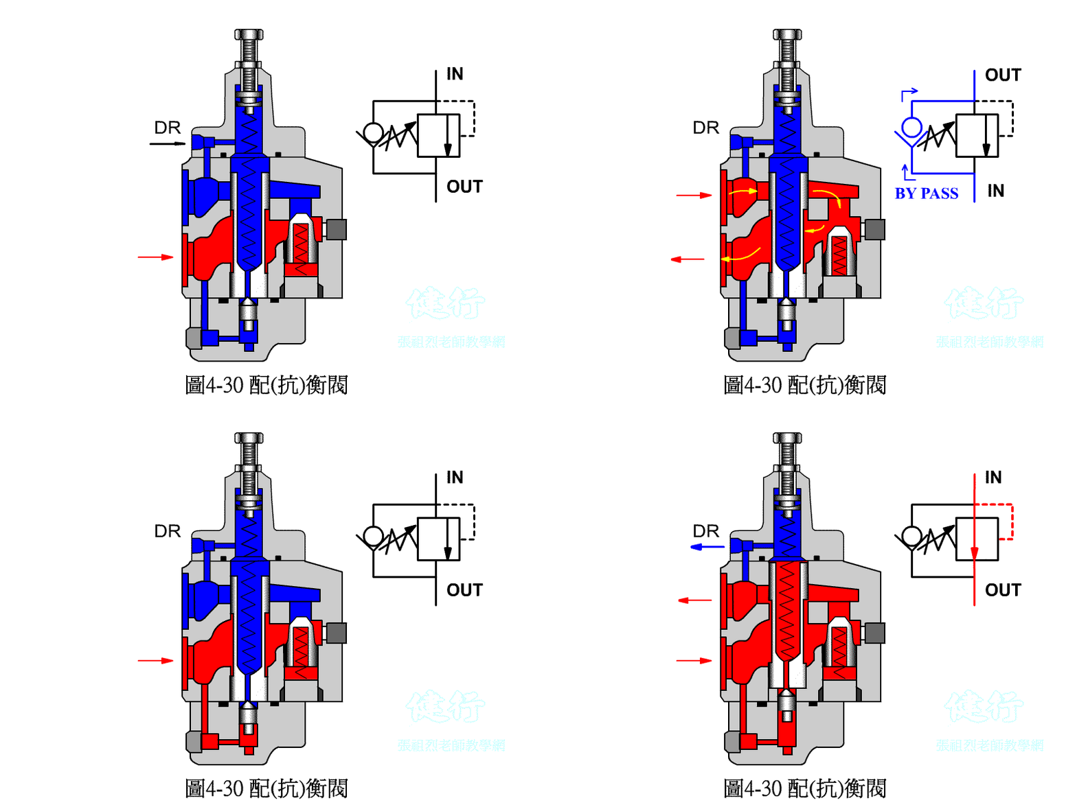
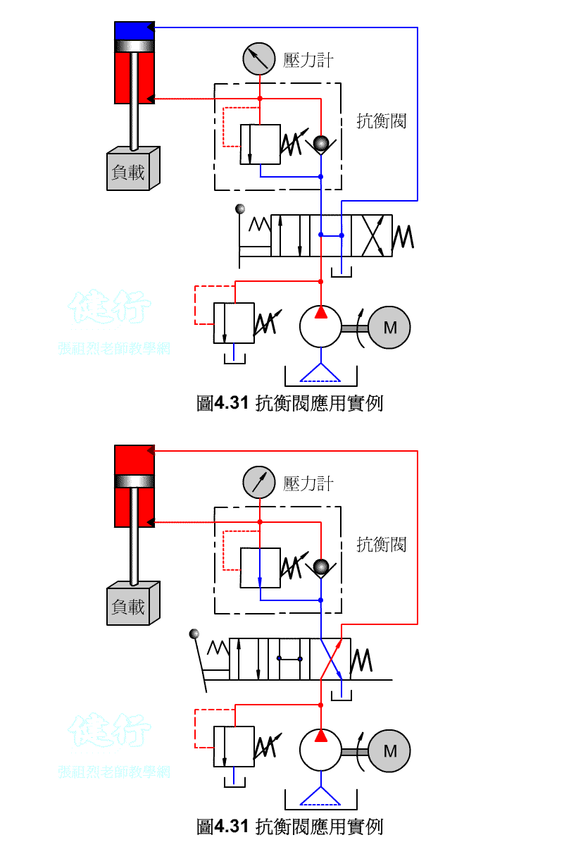
4-3-3 counter valve P427 the
In order to prevent the vertical ram from falling freely due to gravity, a counter-valve is usually installed on the return side of the hydraulic cylinder to apply back pressure to prevent its own weight from falling.
4-4 Booster P428
When the pressure acts on a large area, the generated force is transmitted to a small area, which forms a high-pressure state. The pressure ratio is inversely proportional to the area ratio, and the flow ratio is directly proportional to the area ratio.
the Continuous Booster
GO TO Chapter 5 Flow Control Valve
Go to Zulie teacher teaching network gas hydraulic control practice
