Chapter 4 Circuit Design of Air Pressure Control System
Goto Zulie teacher teaching network Pneumatic hydraulic control practice
4-1 Basic Steps of Circuit Design for Pneumatic System TOP
Step 1: Draw a working diagramP137
Step 2: Write the movement sequence of the pneumatic cylinder in the system
(1) Travel-step diagram TOP
(2) Travel-time diagram (also known as time-travel diagram) TOP
Step 3: Design
the air pressure control circuit according
to the function chart ( or
control signal chart ) TOP
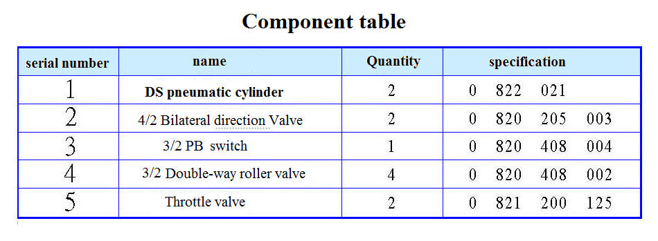
Step 4: Create Component usage table TOP
¡@
The air pressure control circuit discussed in this chapter is mainly based on the traditional pure pneumatic control. Its operating pressure is 3 to 8 kgf / cm2 , the output is between 0 to 3000 kgf, and the speed is between 0.5 to 1.5 m/sec . The following is Several commonly used pure pneumatic circuit design methods.
1 . Intuitive method.
2 . Cascade method.
3 . Cycle step method.
4-2 Intuitive method (Method or Intuition) the TOP
Signal processing method of this design
embodiment has the following ways:
1. The standing-wave
signal [ stagnation (Standing) mode ] :
It is used
for general signals. Installed at the end of the stroke of the pneumatic
cylinder with two-way rollers to generate standing wave signals, as shown in
Figure 4-8.
2. The pulse signal [ overstroke (over travel) mode ] : It is used for interference signal. Installed on the inner side of the end of the stroke of the cylinder with a unidirectional roller. After touching it, it will generate pulse signal. TOP
Intuitive design of the pneumatic circuit can use the method of Figure 4-10 to performone by one TOP
======================================================= =====================
¡@
¡@

(b) Draw a motion picture , which is represented by a displacement time diagram, as shown in Figure 4-12 . At the same time, its exercise sequence is listed in abbreviation: A + B + AB- TOP
(c) Mapping the air pressure circuit TOP
Determine the operation method used by the limit switch ( Unidirectional or bidirectional roller ) : When the signal conflict on the two sides of the direction control element is caused, the interference signal needs to be processed into a pulse signal by overtravel ( that is, the limit switch must be unidirectional Roller and move inward ) . The remaining signal elements are actuated by two-way rollers. May be established below the interference analysis table analysis of
Example 4-2 rivet riveting machine pneumatic control circuit design TOP
(a) Working diagram
(b) Displacement Time FIG TOP
(c) Pneumatic Circuit TOP
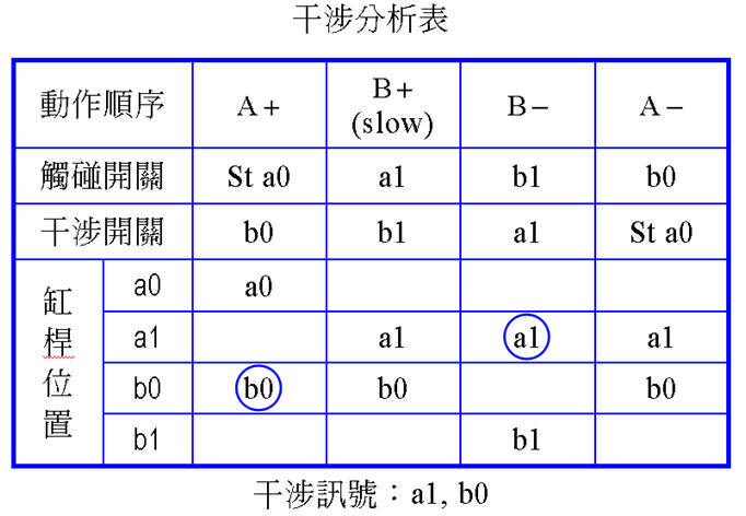
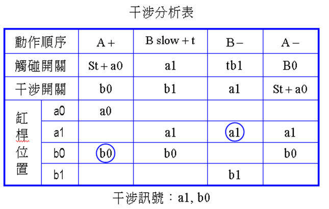
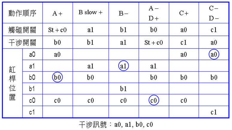
Example 4-3 Design of air pressure control loop for drilling. (a) Displacement time diagram. TOP
exercise sequence is: A + B slow +
B- A-.
¡@
(b) Pneumatic Circuit TOP
The interference signals are a1 and b0 . Change the single roller to move inward in overtravel mode.
Example 4-4 Design of a pneumatic control circuit for automatic drilling and unloading with single cycle operation and continuous processing cycle functions TOP
(a) Working diagram
¡@
(b) Displacement Time FIG TOP
(c) Pneumatic Circuit TOP
Example 4-5 Design of pressure control circuit for chemical cleaning the container. TOP
(a) Working diagram
(b) Displacement Time FIG TOP
(c) Pneumatic Circuit TOP

¡@
The method of cascade uses the signal transfer action of the 4/2 ( or 5/2) bilateral pneumatic valve ( or reversing valve ) to enable complex control to ensure that only one signal is output per action:
Take Figure 4-27 as an example:
How to grade? TOP
Example 4-6 Try to design the following air pressure control circuit by cascade method. TOP
displacement time chart is shown
in Figure 4-33 .
¡@
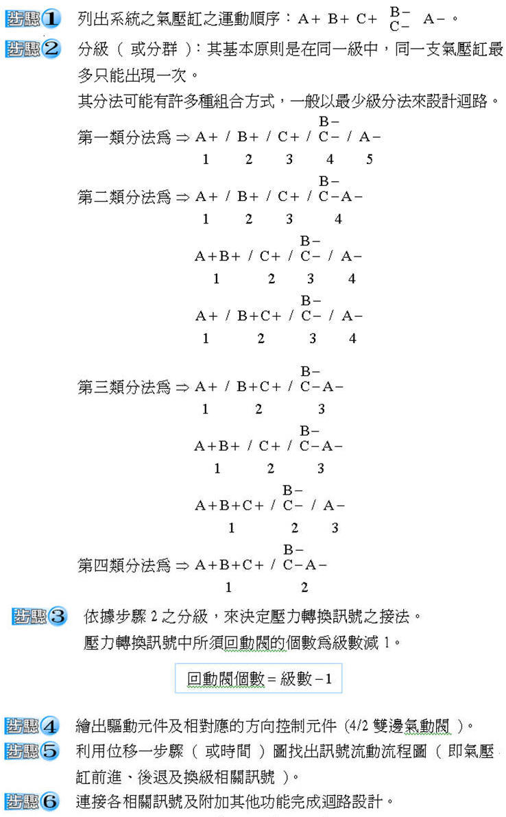
Step 1 : List exercise sequence TOP
Step 2 : Classification. 
Step 3 : Draw the pressure conversion signal.
Step 4 :
Draw the drive element, direction control element and limit switch positions and
name them alphabetically.
¡@
Step 5 : List the signal flow and connect the relevant signals to complete the loop. TOP
Example 4-7 Try to design the air pressure control circuit in the sequence of action diagram. TOP


Example 4-8 Milling working displacement time of milling machine is shown in Figure 4-40. TOP
Example 4-9 The schematic diagram of the bead blasting work and the displacement steps of the casting are shown in Figure 4-43 and 44. TOP


Step 6 : Connect the relevant signals to complete the circuit design. TOP
¡@
The displacement steps of Example 4-10 are shown in Figure 4-47. TOP
The signal flow is: TOP

4-4 Cycle Step Control Circuit Design Method TOP

Example 4-11 Printing logo continuously. Figure 4-51 is its schematic diagram. Figure 4-52 shows the displacement steps. TOP

Step 5 : Find the signal flow. TOP

Step 6 : Connect related signals and add auxiliary conditions to complete the circuit design.
Designed by maximum structure method: TOP

Example 4-12 bent and punched clamp, Figure 4-56 is the schematic diagram of this work. Figure 4-57 is the displacement time chart. TOP
¡@
Step 1 : List
exercise sequences. 
Step 2 : Classification. TOP
Step 3 : Draw the pressure conversion signal.
Step 4 :
Draw the drive elements, direction control elements and corresponding limit
switch positions and name them in alphabetical form.
¡@
Step 5 : Find the signal flow. TOP

Step 6 : Connect the relevant signals, add auxiliary conditions (B , C speed control required,Manual and automatic selection) to complete the circuit design. TOP
¡@
GOTO Chapter 5 Electrical-Pneumatic Control
Goto Zulie teacher teaching network Pneumatic hydraulic control practice