Chapter 1 Introduction to Hydraulics
中文 Orang
indonesia
1-1-1 Basic
Structure of Hydraulic
Control System
1-2
Features of hydraulic
control system
Advantages of
hydraulic devices
Disadvantages of
hydraulic devices
1-3 Basic
Principles of Hydraulic Control System
[ Pascal's
law (Pascal's
Law)]
Hydraulic jack
principle
Flow
change of choke port and orifice
Reynolds number
Laminar flow (Laminar
Flow) ,
turbulence (Turbulent
Flow) pressure
loss and the pipe, the valve
Pressure loss in
the pipeline
Jet (Jet
Flow) and
force (Force)
Thrust and speed of
hydraulic cylinder
1-4 sequence
control (SEQUENCE CONTROL) Basic
Concept
1-4-1 Basic
Structure of Sequence Control System
1-4-2 Application
Examples of Sequence Control
Relationship
between 1-4-3 hydraulic
control and sequence control
FIN
Goto Zulie
teacher teaching network gas
hydraulic control practice
1-1-1 Basic
Structure of Hydraulic
Control System P329 TOP
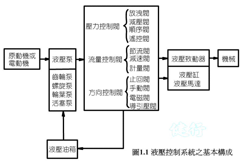
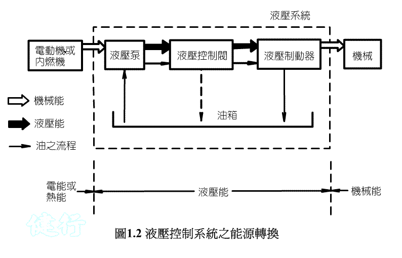
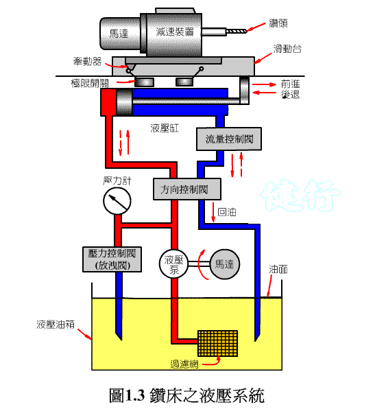
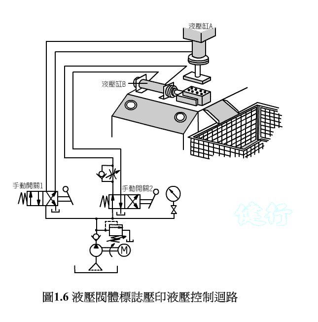
The hydraulic system is composed of the following five parts:
1. Hydraulic
oil tank (oil tank) ;
2. The pump (Hydraulic Pump) ;
3. The hydraulic
control valve (Hydraulic Control
Valve) ;
4. Hydraulic
actuator (hydraulic actuator) ;
5. Hydraulic accessory .
1-1-1 Components
Function of Hydraulic Control System P 331 TOP
( I ) Hydraulic Tank P 331
( Two ) hydraulic
pump (Hydraulic
Pump)
( Three ) hydraulic
control valve (Hydraulic
Control Valve)
( Four ) hydraulic
actuator (Hydraulic
Actuator)
( Five ) hydraulic
parts subsidiary (Hydraulic
Accessory)
 TOP
TOP
 TOP
TOP
 TOP
TOP
 TOP
TOP
 TOP
TOP
 TOP
TOP
Comparison of characteristics of 1-2-1 hydraulic
pressure and air pressure
n1. Compressibility:
The air
is compressible, so it is not easy to control in the control
accuracy, especially at low speed.
n2. Cleanliness:
The compressed
air is clean, but the exhaust gas will have lubricating oil
mist. Leakage of hydraulic oil can cause
contamination.
n3. Pressure
range: Generally,
the air pressure is low and the speed is fast, and most of them
are used for small output and fast impact control.
The hydraulic pressure is high pressure and slow speed, which is
mostly used for high output and high density energy.
n4. Lubricity:
The oil
has lubricity and less wear on the parts; the air pressure
system must be equipped with drying, filtering and oil feeding
devices.
n5. Explosion-proof: hydraulic
oil is flammable, compressed air10bar or
lessThere
is no danger of explosion.
=============================================== ==
n-1. small
size and output ( torque ) large,
high power density (power
density)
n2.Can automatically
adjust the output
n3. It
is easy to achieve stepless control or adjustment of speed, torque,
stroke, etc.
n-4. Overload (over
load) protection
is very simple
n5. Remote
control and easy automation
n6.Can be
used for continuous or intermittent exercise
n-7.
The tool
durability
n8.Good reversibility
=============================================== ==
n1. Poor
piping may cause oil leakage, pollute the environment and
cause fire
n-2. hydraulic
oil ViscosityWill
change due to changes in oil temperature, affecting speed
control
n3. The
installation of pipeline is not as simple as electrical
wiring
n-4. drive actuator
slow
n5. The
horsepower of the motor needs to be increased
n6. High
processing accuracy and installation technology, cost is
more expensive
n7. Others:
If the oil
contains air bubbles, it will cause the hydraulic device to
malfunction. Impurities in the oil can damage
components and cause failures, so a filter is required in
the system to remove the impurities. The
installation cost is high, the volume is large, the weight
is heavy, and there are problems such as hydraulic oil
pollution.
=============================================== ==
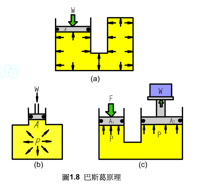
n1. The
direction of pressure is perpendicular to the fluid contact surface .
n2. The
pressure of each point in the fluid in a stationary state should be
equal in all directions.
n3.
In a closed
container, when any point in the liquid is subjected to pressure,
this pressure will be transmitted to other parts of the container
with the same pressure intensity.
 TOP
TOP
 TOP
TOP
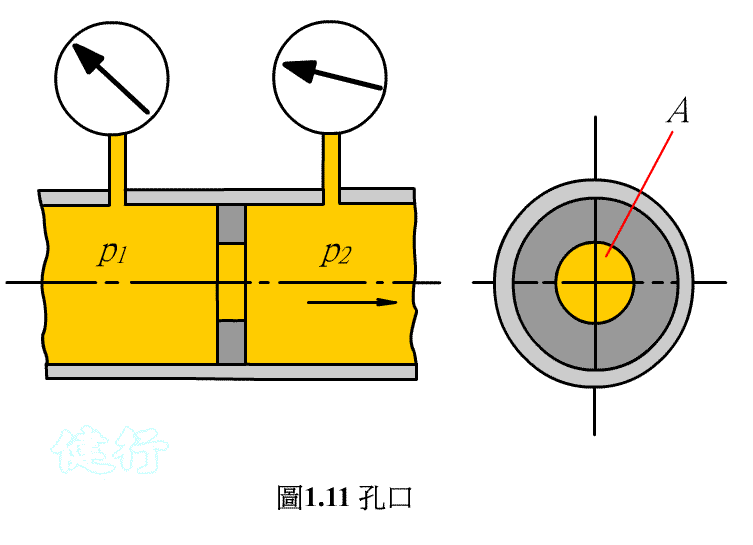
Choke port:
 TOP
TOP
Orifice (Orifice ,
opening limiting ) : P 345 the
TOP
 TOP
TOP
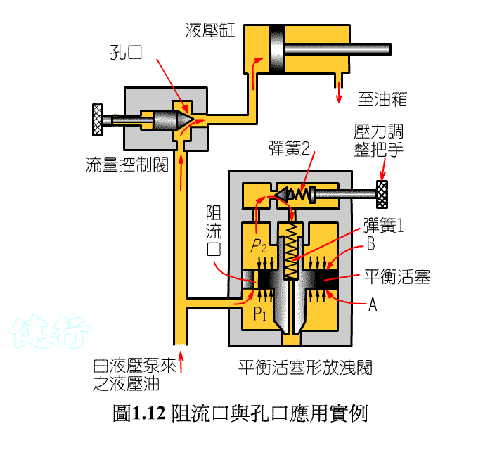
Application examples of choke and orifice P 347 TOP
 TOP
TOP
Turbulent flow: When
the flow velocity increases to a large value, many
small vortices are generated in the flow field,
which is called turbulent flow.
Reynolds number TOP
|
 |
D :
diameter of the inner tube, [m]
 :
Pingjunsudu, [m
/ S] :
Pingjunsudu, [m
/ S]
[rho] :
Density, [kg
/ m . 3 ] [mu] :
viscosity, [kg / m ‧
per S ,
or Pa ‧
per S]
|
Re <2,100 laminar
flow
Re> 4,000 chaos stream
2,100 <Re <4,000 transition
flow
 TOP
TOP
1. Tube friction coefficient
f:
The main loss calculated for large
flow rates is about 1.75 times that of small flow rates, so when a smaller
flow rate is used, it will
have a positive effect on
the reduction of pipes, cavitation and cavitation ( the
pipeline at the pump inlet lift). .
Loss Coefficient of Tube Bend: TOP
 TOP
TOP
Pipe loss
coefficient change the passage cross section: P 350 the
TOP
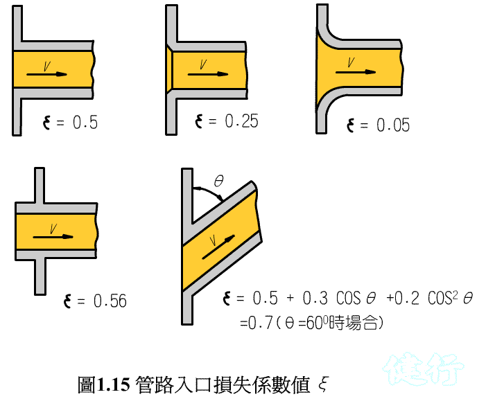
(1) Pipeline
inlet loss coefficient:
 TOP
TOP
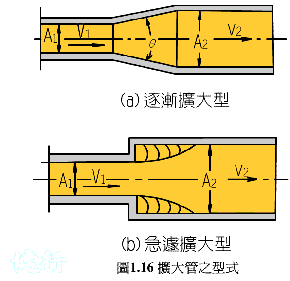
(2) Loss
coefficient of expansion pipe: 351 TOP
 TOP
TOP
(3) Loss
coefficient of reduction tube: P 352 TOP
 TOP
TOP
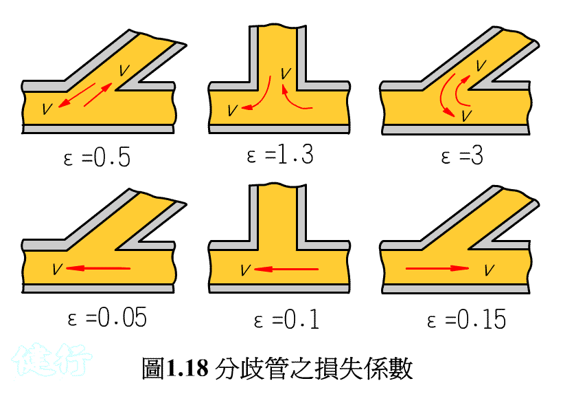
(4) Loss
coefficient of branch pipe: P 352 TOP
 TOP
TOP
There are many types of hydraulic valves and their internal structures are
complicated, so the loss coefficients of the valves are determined by
experiments. For the pressure loss of various valves, you can refer to the
technical information provided by the manufacturer. TOP
 TOP
TOP
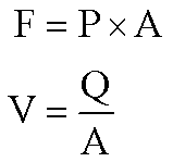
( A ) single-action
hydraulic cylinder (without spring) TOP
 TOP
TOP
( Two ) double-acting
hydraulic cylinder P 356 TOP
A: Piston area
B: effective area of rod end
piston
P1: Pressure
P2: back pressure
Q: Traffic
 TOP
TOP
TOP
 TOP
TOP
 TOP
TOP
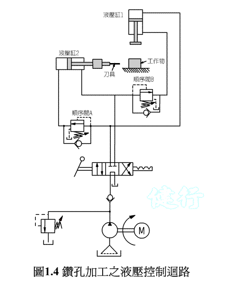
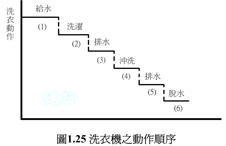
Sequence control system
is a control system capable of performing a series of work sequences P 359
 TOP
TOP
 TOP
TOP
 TOP
TOP
 TOP
TOP
 TOP
TOP
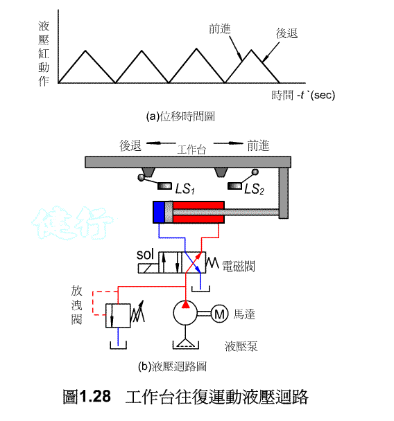
Full hydraulic control is uneconomical
and bulky. Therefore, hydraulic components are used for the
driving components, and the electrical control is adopted for the control
part, which will become a hydraulic
sequential control system with good functions and
high output. At present, many working machines such as lathes,
milling machines, grinders, and handling machines use hydraulic and
electrical controls.
GOTO Chapter
2 Hydraulic Oil Tank and Hydraulic Oil
Goto Zulie
teacher teaching network gas
hydraulic control practice
FIN
 TOP
TOP :
Pingjunsudu, [m
/ S]
 TOP
TOP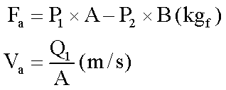 TOP
TOP