Chapter 2 Introduction to Components of Pneumatic Control System
Goto Zulie teacher teaching network Pneumatic hydraulic control practice
Commonly used pneumatic components
2-2 compressed air supply system
An Air compressor for the supply of compressed air pneumatic device, according to the principle can be classified as follows:
¡@
¡@
¡@


¡@
The water content per unit volume of air will increase due to the increase in temperature, and cooling or compression will cause the water molecules in the air to be discharged. The condensed water of the air pressure system therefore often occurs in the gas cylinder and the outlet pipeline.
¡@
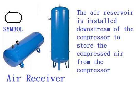
2-4 Air storage and pressure accumulator
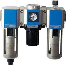
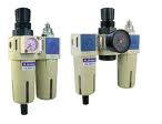
2-6 Conditioning of compressed air
Compressed air conditioning components include air Filters, Pressure regulators and Lubricator, collectively referred to as three-point combination or three-point.

Pressure regulator (Pressure regulating valve)
¡@
2-7 Energy conversion mechanism ( Actuator or drive element )
Components that convert air pressure energy into mechanical energy can be divided into:
1. Linear motion: Pneumatic Cylinder
2. Swing motion: Pneumatic Rotary Cylinder
3. Rotating motion: Pneumatic Motor

Gold Compressor (professional manufacturer of pneumatic automation)
¡@
Special type pneumatic cylinder P54
1. The rodless pneumatic cylinder (Rodless Cylinder)
Features are as follows:
(1) Can shorten the assembly space
(2) Lightweight and durable
(3) Two-way motion is stable
(4) Can produce extra long stroke pneumatic cylinders
(5) Can be directly loaded on the connecting frame
¡@https://www.itsfun.com.tw/%E7%84%A1%E6%A1%BF%E6%B0%A3%E7%BC%B8/wiki-0363002
3. The tandem pneumatic cylinder P57

4. Multi-position air cylinder (Multi-Cylinder) P58
Rotary cylinder P59

Pneumatic Motor P62

2-8 Energy converter (pneumatic - hydraulic conversion system)
( 1 ) Pneumatic- Hydraulic converter
( 2 ) Pneumatic - hydraulic booster
( 3 ) Pneumatic - Hydraulic feed assembly
according to different structures can be divided into 5/3 valve (5/3 valve ) , 3/2 on-off valve (3/2 valve ) ......
like. "Port" refers to the interface of the directional valve,
and "bit" refers to the number of directional valve body changes.
Common code of interface:
P : Compressed air entering the component interface is represented by P ( pressure source interface ) ;
A, B, C : Working pipeline interface of component outlet;
R, S, T : Exhaust interfaces of components;
X, Y, Z : Control signal interface of the component.
¡@
¡@
2-9-1 Various design types of directional control valve
¡@
¡@
2-9-2 The function and characteristics of the direction control valve
¡@
¡@
2-9-3 The control mode of the directional valve
¡@

2-9-4 Solenoid valve, SOL
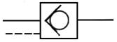
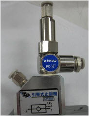
2-10 Check valve ( or Inverse s valve) P83


If there is occasional need for a reverse path, a pilot check valve can be used to open it with pilot pressure.
Pilot check valve
2-11 Shuttle valve P83
¡@
2-13 QUICK EXHAUST VALVE P86
2-14 FLOW CONTROL VALVE P87,
2-15 Timer valve P89

2-16 SILENCER P91
2-17 PRESSURE SWITCH P92
2-18 COUNTER P93

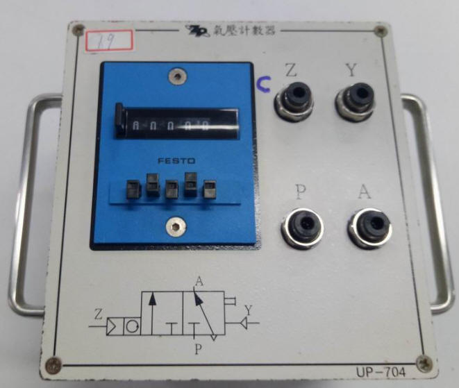
+ and - type Pneumatic Counter
2-19 Quick connector P94
GOTO Chapter 3 Basic Pnaeumatic Control Circuit
Goto Zulie teacher teaching network Pneumatic Hydraulic control practice