Chapter 3 Basic Pneumatic Control Circuit
Goto Zulie teacher teaching network Pneumatic hydraulic control practice
¡@
+

3-1-3 signal flow of Pneumatic control circuit
The one-way roller control valve only outputs the control signal when it touches in the forward direction , but no signal occurs in the reverse direction .
3-3 Basic pneumatic circuit diagram P107
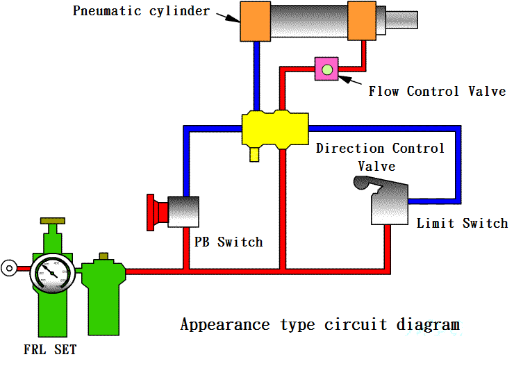
3-3-1 Direct control of a pneumatic cylinder
( a ) using
the push button switch control proceeds directly to a single-acting pneumatic
cylinder of the (extended) and
return (return
line)
( b ) Direct control of double-acting pneumatic cylinder forward and backward P108
( c ) the circuit of the pneumatic cylinder can be sped at any position in the middle P110
3-3-2 Actuator speed control P110
( 1 ) Deceleration control
1. The intake throttling (meter-in) control
2. Exhaust throttle (meter-out) mode control P112
( 2 ) Acceleration control P115
3-3-3 Application of Shuttle valve circuit P117
Equivalent electrical circuit : P117
Parallel
circuit
¡@¡@
3-3-4 Dual pressure valve circuit application
Equivalent electrical circuit: P119
Series
circuit
¡@¡@
3-3-5 Pneumatic cylinder indirect control P121
( 1 ) Indirect
control using a single-sided pneumatic valve
P121
¡@
( 2 ) Indirectly Controlled using bilateral pneumatic valves P122
( 3 ) automatic return of pneumatic cylinder P123
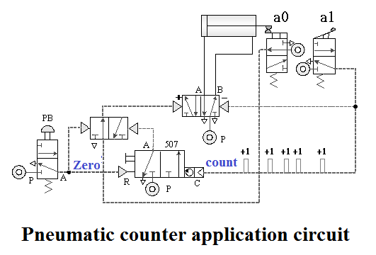
( 4 ) Continuous reciprocating motion of the pneumatic cylinder P123
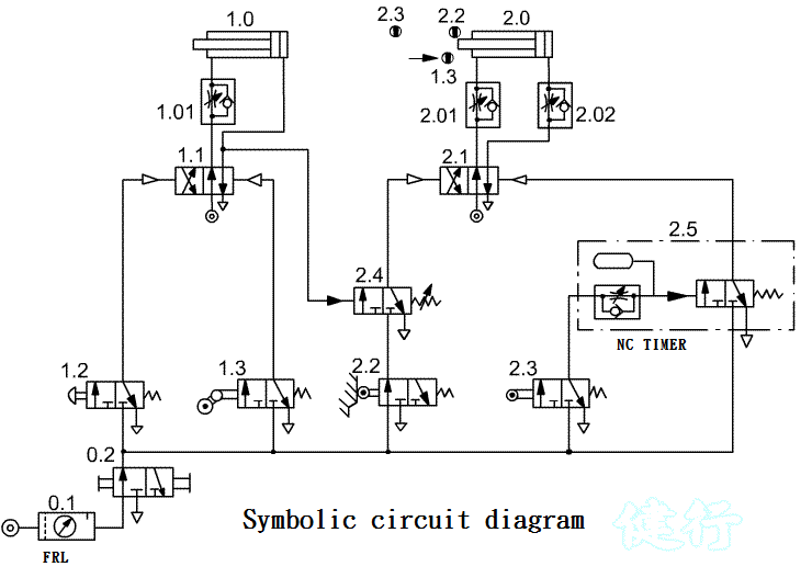
3-3-6 Timing valve circuit application P124
( a ) Delayed
return circuit of pneumatic cylinder ( 1 ) P124
¡@
( b ) Delayed return circuit of pneumatic cylinder ( 2 ) P127
( c ) Circuit of delayed forward and delayed return of pneumatic cylinder P128
3-3-7 Safety circuit operated by both hands P129
(a) Circuit
operated by both hands
P129
¡@
(b) Safety circuit operated by both hands P130
3-3-8 Control loop for automatic (continuous) and manual (single) cycle processing P131
3-3-9 Emergency Management P132
( a ) Urgent return immediately
( b ) Emergency s in place, continue unfinished action after release P133
( c ) Emergency s on the spot, return first after release and then restart P134.
After-class exercises: manual/automatic single-cylinder reciprocating delay return control circuit

Chapter 4 Circuit Design of Pressure Control System
Goto Zulie teacher teaching network Pneumatic hydraulic control practice