ˇ@
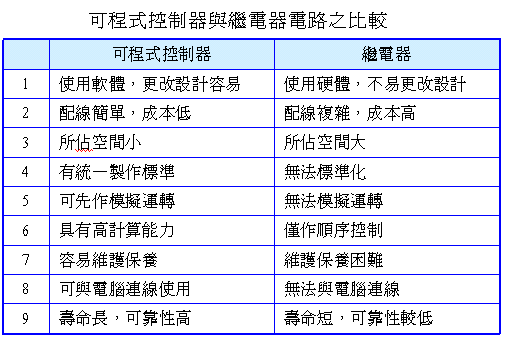
6-1 Comparison of Programmable Controller and Relay Circuit
ˇ@
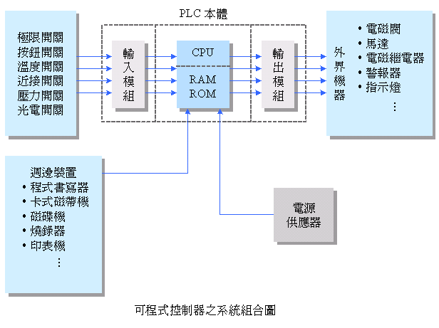
6-2
ˇ@
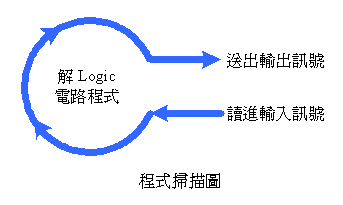
The software program scans continuously. The time required for each scan is called the scan time. The shorter the scan time, the faster its execution.
ˇ@

ˇ@
ˇ@
n1. Analog / digital (A / D) , digital / analog (D / A) conversion module
the n-2. High Speed Counter module
n3. Proportional, Integral and differential control module (PID Control Unit)
n-4. Computer link module (Computer Link Unit)
ˇ@
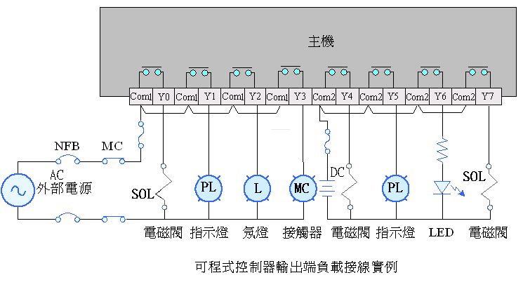
6-4 Programmable controller wiring method
(1)Input
terminal wiring method
ˇ@
ˇ@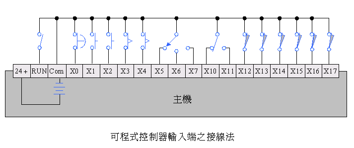 ˇ@
ˇ@
(2) Wiring method of output terminal
ˇ@
Special relay:
nM8000 operation monitoring ( ON during program RUN )
nM8002 initial pulse ( ON one SCAN during program RUN )
nM8011 0.01 second pulse
nM8012 0.1 second pulse
nM8013 1 second pulse
nM8030 BATTERY.V LED OFF
n WhenM8033 PLC ss, all outputs are maintained
nM8034 full output disabled
nM8039 fixed scan
nM8040 step ladder movement prohibition
ˇ@
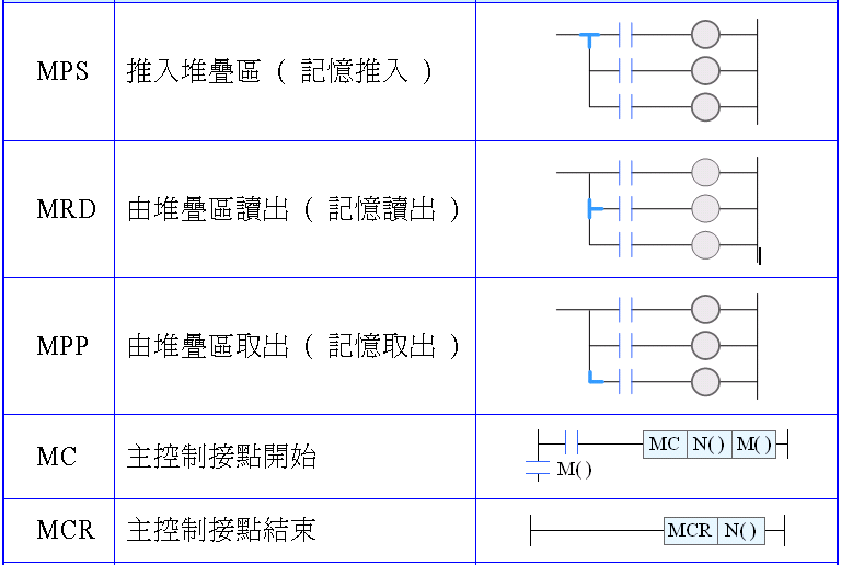
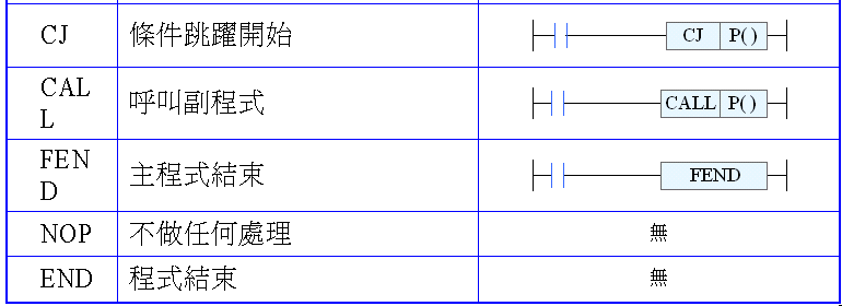
ˇ@
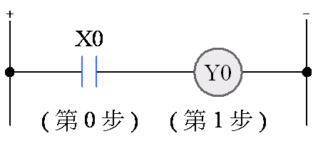
|
Address
|
PLC
Code
|
Number
|
|
0
|
LD
|
X0
|
|
1
|
OUT
|
Y0
|
|
2
|
END
|
ˇ@
ˇ@

|
Address
|
PLC
Code
|
Number
|
|
0
|
LDI
|
X0
|
|
1
|
OUT
|
Y0
|
|
2
|
END
|
ˇ@
ˇ@
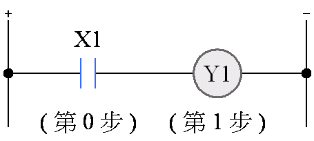
|
Address
|
PLC
Code
|
Number
|
|
0
|
LD
|
X1
|
|
1
|
OUT
|
Y1
|
|
2
|
END
|
ˇ@
ˇ@
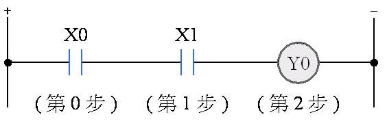
|
Address
|
PLC
Code
|
Number
|
|
0
|
LD
|
X0
|
|
1
|
AND
|
X1
|
|
2
|
OUT
|
Y0
|
|
3
|
END
|
ˇ@
ˇ@

|
Address
|
PLC
Code
|
Number
|
|
0
|
LD
|
X0
|
|
1
|
ANI
|
X1
|
|
2
|
OUT
|
Y0
|
|
3
|
END
|
ˇ@
ˇ@
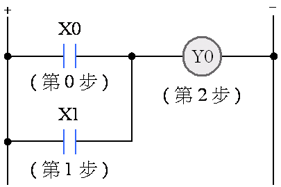
|
Address
|
PLC
Code
|
Number
|
|
0
|
LD
|
X0
|
|
1
|
OR
|
X1
|
|
2
|
OUT
|
Y0
|
|
3
|
END
|
ˇ@
ˇ@
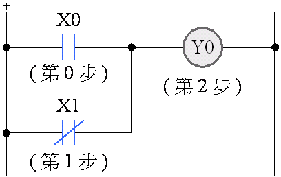
|
Address
|
PLC
Code
|
Number
|
|
0
|
LD
|
X0
|
|
1
|
ORI
|
X1
|
|
2
|
OUT
|
Y0
|
|
3
|
END
|
ˇ@
ˇ@
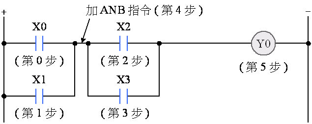
ˇ@
|
Address
|
PLC
Code
|
Number
|
|
0
|
LD
|
X0
|
|
1
|
OR
|
X1
|
|
2
|
LD
|
X2
|
|
3
|
OR
|
X3
|
|
4
|
ANB
|
|
|
5
|
OUT
|
Y0
|
|
6
|
END
|
ˇ@
ˇ@
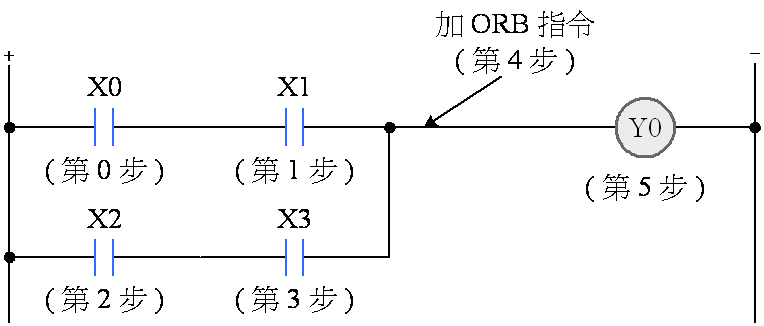
|
Address
|
PLC
Code
|
Number
|
|
0
|
LD
|
X0
|
|
1
|
AND
|
X1
|
|
2
|
LD
|
X2
|
|
3
|
AND
|
X3
|
|
4
|
ORB
|
|
|
5
|
OUT
|
Y0
|
|
6
|
END
|
ˇ@
ˇ@

|
Address
|
PLC
Code
|
Number
|
|
0
|
LDI
|
M1
|
|
1
|
AND
|
X0
|
|
2
|
OR
|
X1
|
|
3
|
OUT
|
M0
|
|
4
|
LD
|
M0
|
|
5
|
OUT
|
Y0
|
|
6
|
LD
|
X2
|
|
7
|
OUT
|
M1
|
|
8
|
END
|
ˇ@
ˇ@
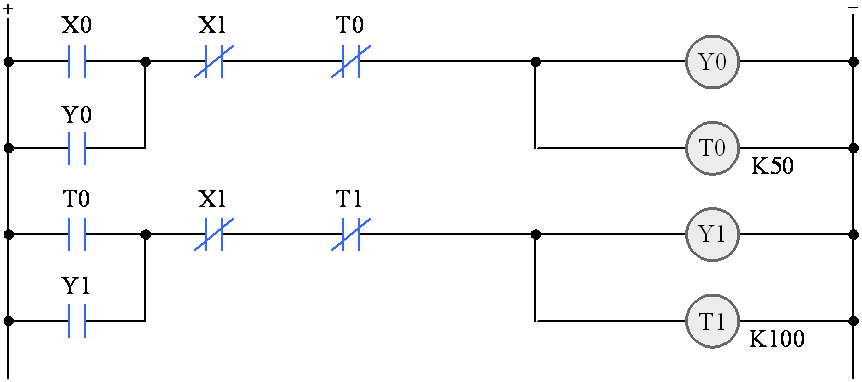
|
Address
|
PLC
Code
|
Number
|
Address
|
PLC
Code
|
Number
|
|
0
|
LD
|
X0
|
9
|
OR
|
Y1
|
|
1
|
OR
|
Y0
|
10
|
ANI
|
X1
|
|
2
|
ANI
|
X1
|
11
|
ANI
|
T1
|
|
3
|
ANI
|
T0
|
12
|
OUT
|
Y1
|
|
4
|
OUT
|
Y0
|
13
|
OUT
|
T1
|
|
5
|
OUT
|
T0
|
K
|
100
|
|
|
K
|
50
|
16
|
END
|
||
|
8
|
LD
|
T0
|
ˇ@
ˇ@
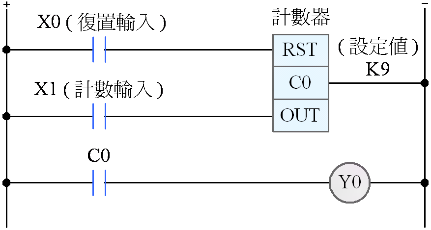
|
Address
|
PLC
Code
|
Number
|
|
0
|
LD
|
X0
|
|
1
|
RST
|
C0
|
|
3
|
LD
|
X1
|
|
4
|
OUT
|
C0
|
|
K
|
9
|
|
|
7
|
LD
|
C0
|
|
8
|
OUT
|
Y0
|
|
9
|
END
|
ˇ@
ˇ@
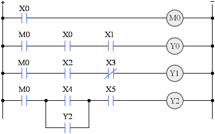
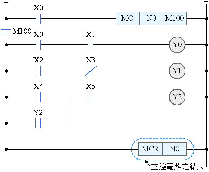
|
Address
|
PLC
Code
|
Number
|
|
0
|
LD
|
X0
|
|
1
|
MC
(N) 0
|
M100
|
|
4
|
LD
|
X0
|
|
5
|
AND
|
X1
|
|
6
|
OUT
|
Y0
|
|
7
|
LD
|
X2
|
|
8
|
ANI
|
X3
|
|
9
|
OUT
|
Y1
|
|
10
|
LD
|
X4
|
|
11
|
OR
|
Y2
|
|
12
|
AND
|
X5
|
|
13
|
OUT
|
Y2
|
|
14
|
MCR
|
(N) 0
|
|
16
|
END
|
ˇ@
ˇ@
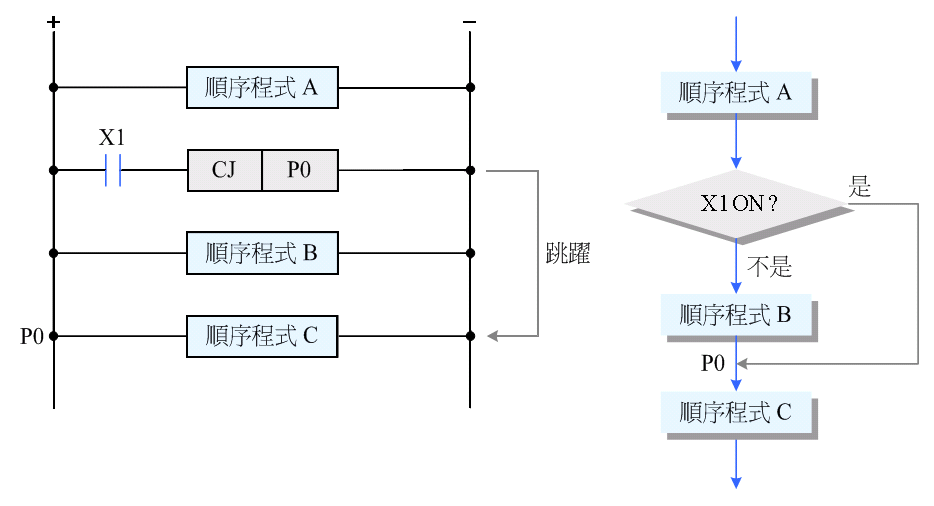
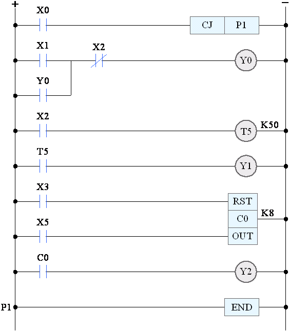
|
Address
|
PLC Code
|
Number
|
Address
|
PLC Code
|
Number
|
|
0
|
LD
|
X0
|
12
|
OUT
|
Y1
|
|
1
|
CJ
|
P1
|
13
|
LD
|
X3
|
|
3
|
LD
|
X1
|
14
|
RST
|
C0
|
|
4
|
OR
|
Y0
|
16
|
LD
|
X5
|
|
5
|
ANI
|
X2
|
17
|
OUT
|
C0
|
|
6
|
OUT
|
Y0
|
K
|
8
|
|
|
7
|
LD
|
X2
|
20
|
LD
|
C0
|
|
8
|
OUT
|
T5
|
twenty one
|
OUT
|
Y2
|
|
K
|
50
|
twenty two
|
P1
|
||
|
11
|
LD
|
T5
|
twenty three
|
END
|
ˇ@
ˇ@
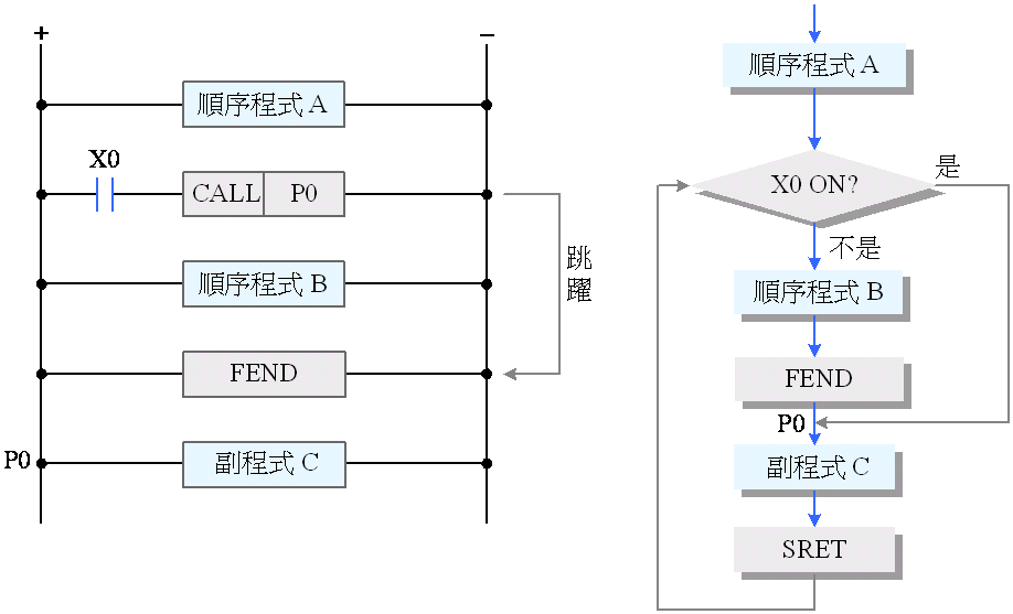

|
Address
|
PLC Code
|
Number
|
Address
|
PLC Code
|
Number
|
|
0
|
LD
|
X0
|
11
|
ANI
|
Y0
|
|
1
|
CALL
|
P0
|
12
|
OUT
|
Y1
|
|
3
|
LD
|
X1
|
13
|
FEND
|
|
|
4
|
OR
|
Y0
|
14
|
P0
|
|
|
5
|
ANI
|
X2
|
15
|
LD
|
X2
|
|
6
|
ANI
|
Y1
|
16
|
OUT
|
T5
|
|
7
|
OUT
|
Y0
|
K
|
50
|
|
|
8
|
LD
|
X3
|
19
|
LD
|
T5
|
|
9
|
OR
|
Y1
|
20
|
OUT
|
Y2
|
|
10
|
ANI
|
X2
|
twenty one
|
SRET
|
ˇ@
ˇ@
ˇ@
ˇ@
ˇ@
|
Address
|
PLC Code
|
Number
|
|
0
|
LD
|
X0
|
|
1
|
OR
|
Y0
|
|
2
|
ANI
|
X1
|
|
3
|
OUT
|
Y0
|
|
4
|
END
|
ˇ@
|
0
|
LDI
|
X0
|
|
1
|
SET
|
Y0
|
|
2
|
LDF
|
X1
|
|
3
|
RST
|
Y0
|
|
4
|
END
|
ˇ@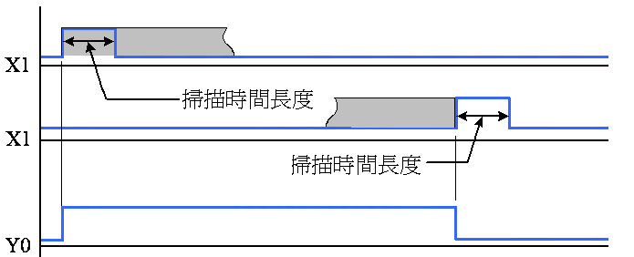
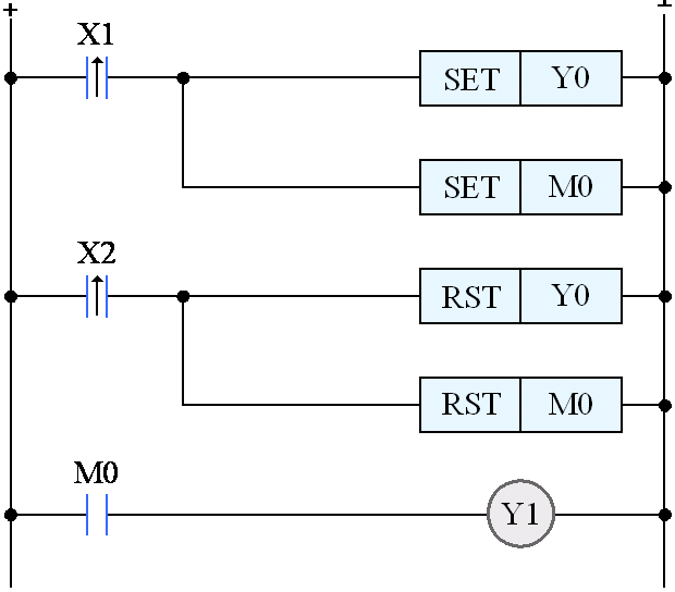
|
Address
|
PLC
Code
|
Number
|
|
0
|
LDI
|
X1
|
|
1
|
SET
|
Y0
|
|
2
|
SET
|
M0
|
|
3
|
LDI
|
X2
|
|
4
|
RST
|
Y0
|
|
5
|
RST
|
M0
|
|
6
|
LD
|
M0
|
|
7
|
OUT
|
Y1
|
|
8
|
END
|
ˇ@ˇ@
nUsingA programmable controller to design a software circuit, follow these steps:
n1. List and number all input and output contacts.
n2. Draw the overall control circuit diagram of the control system.
n3. Change the control circuit to a programmable controller circuit.
n4. Transform the circuit into a logic instruction program.
n5. Write the instruction program into the programmable controller.
n6. Analog control action, if there is deviation, correct it.
ˇ@
ˇ@
6-7 Programmable
Controller Application Example
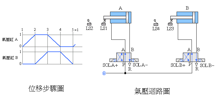
Example 6-1 Pneumatic
Cylinder Reciprocating
ˇ@

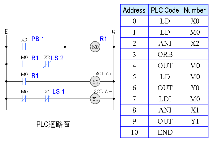
ˇ@
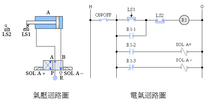
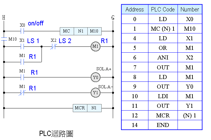
ˇ@

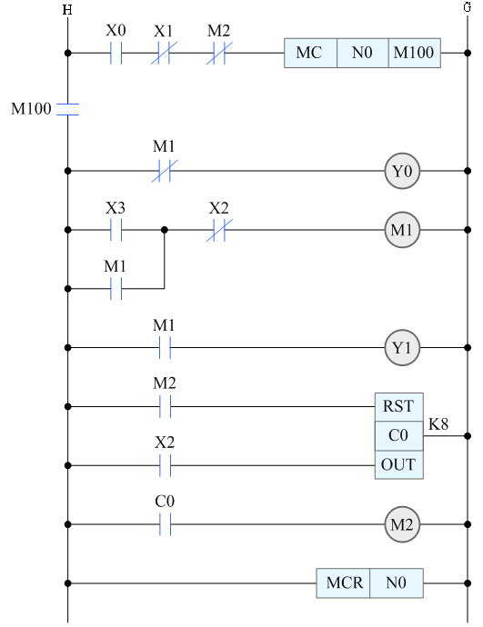
ˇ@
|
Address
|
PLC Code
|
Number
|
Address
|
PLC Code
|
Number
|
|
0
|
LD
|
X0
|
13
|
OUT
|
Y1
|
|
1
|
ANI
|
X1
|
14
|
LD
|
M2
|
|
2
|
ANI
|
M2
|
15
|
RST
|
C0
|
|
3
|
MC (N) 0
|
M100
|
17
|
LD
|
X2
|
|
6
|
LDI
|
M1
|
18
|
OUT
|
C0
|
|
7
|
OUT
|
Y0
|
K
|
8
|
|
|
8
|
LD
|
X3
|
twenty one
|
LD
|
C0
|
|
9
|
OR
|
M1
|
twenty two
|
OUT
|
M2
|
|
10
|
ANI
|
X2
|
twenty three
|
MCR
|
(N) 0
|
|
11
|
OUT
|
M1
|
25
|
END
|
|
|
12
|
LD
|
M1
|
ˇ@
ˇ@
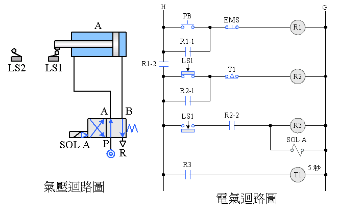

ˇ@
ˇ@

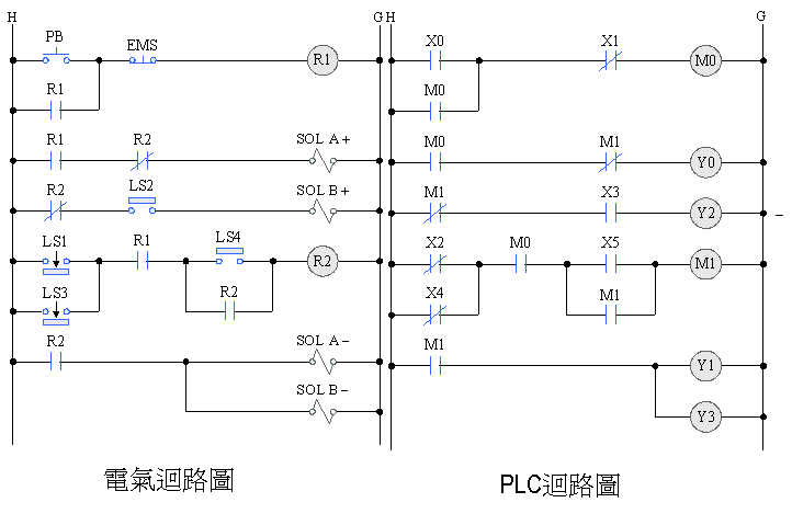
|
Address
|
PLC Code
|
Number
|
Address
|
PLC Code
|
Number
|
|
0
|
LD
|
X0
|
11
|
ORI
|
X4
|
|
1
|
OR
|
M0
|
12
|
AND
|
M0
|
|
2
|
ANI
|
X1
|
13
|
LD
|
X5
|
|
3
|
OUT
|
M0
|
14
|
OR
|
M1
|
|
4
|
LD
|
M0
|
15
|
ANB
|
|
|
5
|
ANI
|
M1
|
16
|
OUT
|
M1
|
|
6
|
OUT
|
Y0
|
17
|
LD
|
M1
|
|
7
|
LDI
|
M1
|
18
|
OUT
|
Y1
|
|
8
|
AND
|
X3
|
19
|
OUT
|
Y3
|
|
9
|
OUT
|
Y2
|
20
|
END
|
|
|
10
|
LDI
|
X2
|
ˇ@
ˇ@
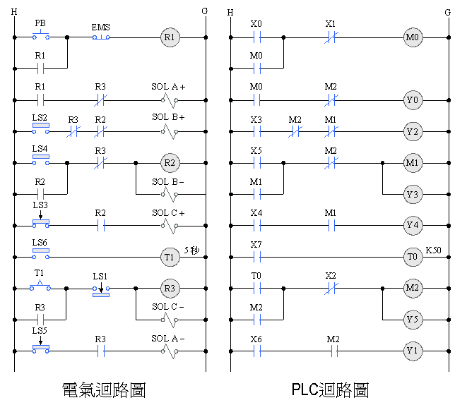
ˇ@

|
Address
|
PLC Code
|
Number
|
Address
|
PLC Code
|
Number
|
|
0
|
LD
|
X0
|
13
|
OUT
|
M1
|
|
1
|
ANI
|
X1
|
14
|
LD
|
M1
|
|
2
|
MC (N) 0
|
M100
|
15
|
OUT
|
Y1
|
|
5
|
LDI
|
M1
|
16
|
LD
|
M1
|
|
6
|
OUT
|
Y0
|
17
|
AND
|
X2
|
|
7
|
LD
|
X3
|
18
|
OUT
|
Y3
|
|
8
|
ANI
|
M1
|
19
|
LD
|
M1
|
|
9
|
OUT
|
Y2
|
20
|
AND
|
X4
|
|
10
|
LD
|
X5
|
twenty one
|
OUT
|
M2
|
|
11
|
OR
|
M1
|
twenty two
|
MCR
|
(N) 0
|
|
12
|
ANI
|
M2
|
twenty four
|
END
|
ˇ@
ˇ@

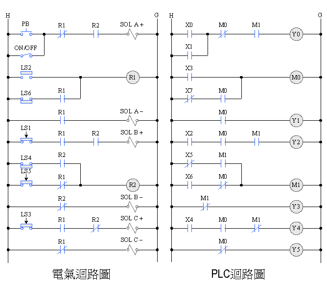
|
Address
|
PLC Code
|
Number
|
Address
|
PLC Code
|
Number
|
|
0
|
LD
|
X0
|
16
|
LD
|
X4
|
|
1
|
OR
|
M0
|
17
|
AND
|
M1
|
|
2
|
ANI
|
X1
|
18
|
OUT
|
Y4
|
|
3
|
OUT
|
M0
|
19
|
LD
|
X7
|
|
4
|
LD
|
M0
|
20
|
OUT
|
T0
|
|
5
|
ANI
|
M2
|
K
|
5
|
|
|
6
|
OUT
|
Y0
|
twenty
three
|
LD
|
T0
|
|
7
|
LD
|
X3
|
twenty
four
|
OR
|
M2
|
|
8
|
ANI
|
M2
|
25
|
ANI
|
X2
|
|
9
|
ANI
|
M1
|
26
|
OUT
|
M2
|
|
10
|
OUT
|
Y2
|
27
|
OUT
|
Y5
|
|
11
|
LD
|
X5
|
28
|
LD
|
X6
|
|
12
|
OR
|
M1
|
29
|
AND
|
M2
|
|
13
|
ANI
|
M2
|
30
|
OUT
|
Y1
|
|
14
|
OUT
|
M1
|
31
|
END
|
|
|
15
|
OUT
|
Y3
|
ˇ@
ˇ@

|
Address
|
PLC Code
|
Number
|
Address
|
PLC Code
|
Number
|
|
0
|
LD
|
X0
|
16
|
LDI
|
X5
|
|
1
|
OR
|
X1
|
17
|
AND
|
M1
|
|
2
|
ANI
|
M0
|
18
|
LD
|
X6
|
|
3
|
AND
|
M1
|
19
|
ANI
|
M0
|
|
4
|
OUT
|
Y0
|
20
|
ORB
|
|
|
5
|
LD
|
X3
|
twenty
one
|
OUT
|
M1
|
|
6
|
LDI
|
X7
|
twenty
two
|
LDI
|
M1
|
|
7
|
AND
|
M0
|
twenty
three
|
OUT
|
Y3
|
|
8
|
ORB
|
twenty
four
|
LD
|
X4
|
|
|
9
|
OUT
|
M0
|
25
|
AND
|
M0
|
|
10
|
LD
|
M0
|
26
|
ANI
|
M1
|
|
11
|
OUT
|
Y1
|
27
|
OUT
|
Y4
|
|
12
|
LD
|
X2
|
28
|
LDI
|
M0
|
|
13
|
AND
|
M0
|
29
|
OUT
|
Y5
|
|
14
|
AND
|
M1
|
30
|
END
|
|
|
15
|
OUT
|
Y2
|
ˇ@Goto Zulie teacher teaching networ Pneumatic hydraulic control practice
GOTO Hydraulics: Chapter 1 Introduction to Hydraulics

